Contact Fax
0552-4070672

PRODUCTS

4. Installation and connection definition
4.1. All transmitter via digital calibration, the different between the transmitter has the complete consistency and interchangeability.
4.2. Installation temperature transmitter, the need to unscrew header back cover, the cable from the electrical interface access, according to the connection correctly defined. Wiring is completed, please send back cover screw to ensure waterproof.
Install temperature transmitter (1) 4.3. The line pipe, pressure, discharge empty running. On the pipe opening phi 26; (2) to protect the pipe sleeve insertion depth from opening phi 26 L1 ', and then along the hole week seal welding on the pipe; (3) the protective sleeve tube into the heat conduction oil, about 2/5 of the volume of; (4) the temperature transmitter probe insert to protect casing, adjust good header direction, with wrench will union tighten, pipeline transport.
Definition 4.4. Terminal:
Eight core wires green definition. (1) - 24 v power supply + 1, 5 feet, 0 v - 2, 6 foot, 3, 7 feet - 485 _a, 4, 8 feet - 485 _b.
Site 485 communication, need access to 1234 feet, 1-2 power supply, communication A - 3-4 B.
Scene 4-20 ma communication, you just need to access 1 to 2 feet.

(2)4-20 ma main signal into two wire system, the RS485 interface, the need to pay attention to while using RS485 and 4-20 ma digital communication grid number cannot exceed 10. Don't add termination resistors RS485 interface, otherwise it will cause 4-20 ma current jump, 4-20 ma current signal. If only use RS485 signals, there is no limit to the number of parallel, up to and after 255.
Note:
1. The current commercially available passive RS485 converter drive ability is limited, so in parallel quantity is large, the use of the active isolation type RS485 interface.
2. Because of the grid, the board inside the RS485 bus is not set bus matching resistance, no pull up and down the resistance, if the customer USES RS485 interface also do not have to pull up and down the resistance, static level could lead to a bus uncertain, RS485 bus has a wrong data. So customers or system integrator should be on the outside of the bus matching resistance and the resistance to set the bus pulled up and down the static state.

4.6 meter communication basic information site Settings
Also has a built-in instrument protocol. Support MODBUS_RTU agreement, adopt green free software installation technology, using the dynamic link library will automatically extract the needed, so please in the computer antivirus software set the software to white list. To prevent the security software to prevent normal operation of the software.
Software support serial port in the range of 1 to 15, if you are using a USB serial port, please amend the port number to 1 to 15.
Other tested, is currently in use more USB/RS485 converter, inside there are many different kinds of USB conversion chip, now find FDT232 chip converter using devices need to set of drive, otherwise it will lead to the software can't read data transmitter. Settings page is as follows:
 FDT232软件的驱动高级设置,在设备管理器中打开,可以看到有一个BM选项,此设置应该改为1,一般软件默认的是15,所以必须要修改次设置才可以正常使用串口。 其他芯片的USB转换器目前没有发现此类问题。
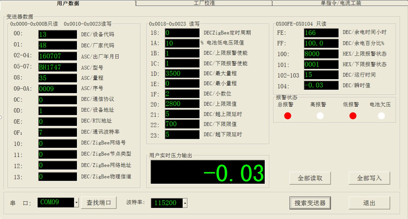
1. Search for port:
Software can automatically search for the machine available port, please select the correct port number, the selection and match the baud rate in the transmitter, click on the search button to search online transmitter, software there are search results suggest the bottom. List the computer all of the available port Numbers, if there is a dynamic plug USB virtual port, you can click on "find a serial port" to update the information.
2. "search transmitter:
Transmitter is to search online, search address range 1-255. The search to tip in the status bar. Search to an early end to search again, please click on the can. Pay attention to select baud rate frequency band. Search only in view of the current set baud rate range.
3. "read all" :
After the search stops software will automatically to first read all the parameters in the transmitter. And continuous reading the state of alarm, real-time measurement and instrumentation, ADC values. Click on the all read all button can also update the current data.
4. "write all" :
All the data modification is finished click on "write" can be saved to the transmitter.
Note that the software blue text box to support customer modify the content above, the red box for the default data transmitter.
Additional information:
Software according to the agreement of customer, has said, according to a separate address said way data frame at the back of the data type show the type of the data,
DEC said decimal data. HEX, hexadecimal data characters represent text characters, is assic yards. Detailed protocols and data need to refer the customer to provide the text of the agreement.
4.7. Panel key configuration
This circuit has three buttons and LCD display window:
7.1 panel buttons:
M key function mainly mode key, is the switching data and menu. Mode button on the transmitter not setting mode long press reset function performs the main variables, whether need to S and Z key to select.
S key functions mainly data and functionality. In the setup mode, long press the S key will enter the high active transmitting range setting mode. At this point need to pay attention to sense pressure.
The Z key function mainly data shift and reduction function. In the long set mode according to the Z key into active zero setting mode.
In the measurement mode, click the M key click enter password mode, need a password to enter setup mode. Password is not correct, the transmitter will exit to measurement mode.
Circuit board with active range migration scale and zoom function for migration. Passive setup requires users to enter configuration mode Settings.
The following conventions button state:
S key click for short: S Z key click: S M key single press for: M
M bond length for ML
S long press for: long press for ZL SL Z key
7.2 the following is a passive configuration panel key setup process:
Panel layout diagram:
 Set the flow chart of the menu:

In the END the menu, press the M key to exit the setup mode, and save the data. Under the other menu, long press the M key will exit the Settings mode, but you don't save the data.
Figure OUT the menu has two, one is the FIX menu, one is the output linearization.
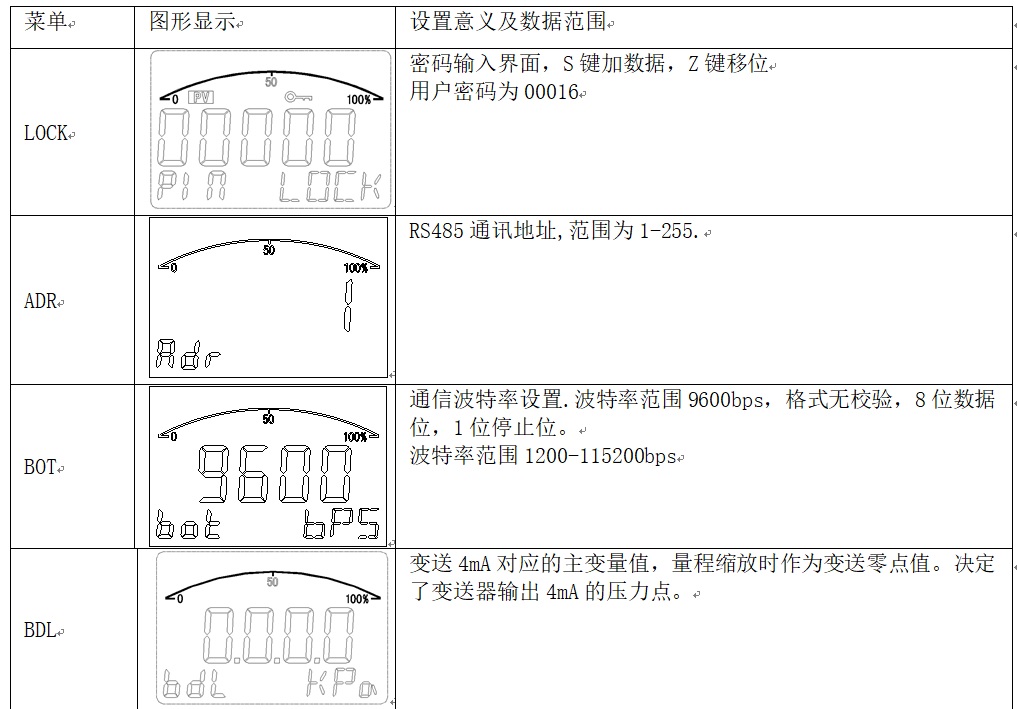
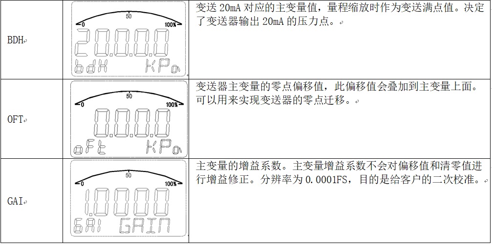
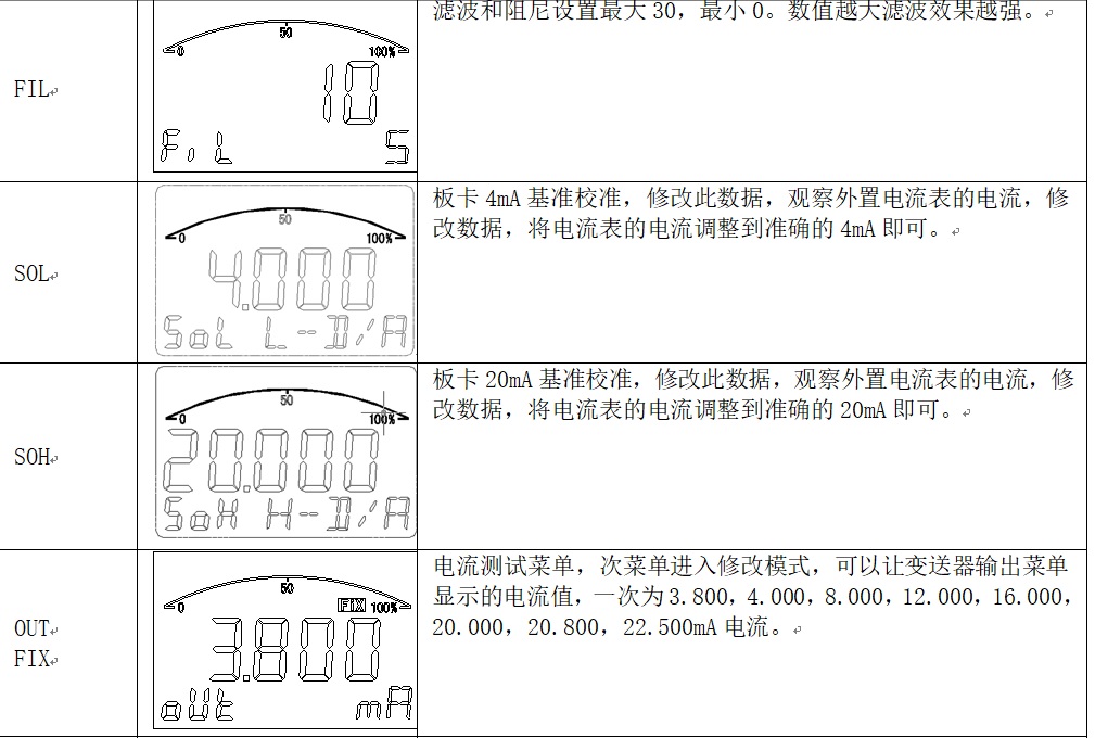
Above Settings menu, the corresponding menu data:

2.Active reset migration and the main variables
Into the active migration and the main variables are reset when the need to work in normal mode to enter.
Active migration Settings to ensure that the pressure is effective. Otherwise the output of the transmitter is abnormal.
General reset has a limit, the main variable value needs to near zero or near zero pressure, limited scope of 10%, more than this range will not carry out clear operation.

3.切换显示:
a)屏幕的主屏显示和付屏显示区有多种显示功能,主屏显示有压力值显示,百分比显示,电流显示三种。
b)付屏显示有温度显示和从机地址显示两种选择。温度值来自于电路板卡上的温度传感器
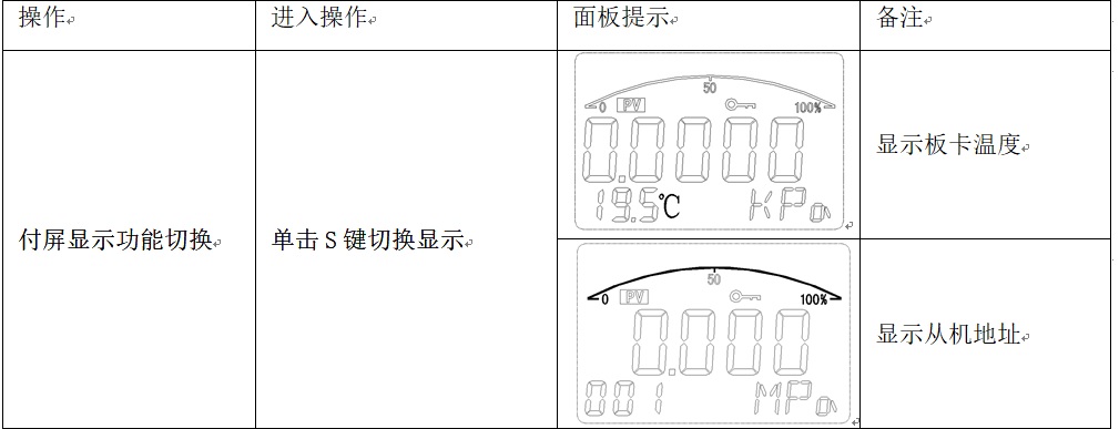
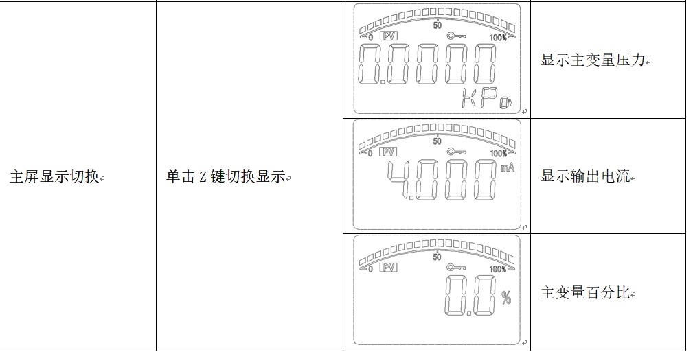
Display switch can be done at any time, every time after power on display mode depends on the software at the time of the last save mode value, set on the display mode in panel key at the next will be cleared when power supply drop.
Liquid crystal display screen has a battery display at the top right-hand corner. Battery five progress bar, article number said the battery is enough. After the battery voltage is lower than 3.0 V battery will automatically cut off the output.
The transducer adopts double power supply system, in addition to the normal power supply and a built-in battery power supply mode, through SW transmitter switch is on battery power, the transducer working in battery mode. Such as built-in battery capacity of 2000 ma/h when the battery power supply can reach 300 hours, the longest work time is about 12.5 days. Whether the built-in battery, if the external power on, the instrument will automatically priority use of external power supply, and output 4-20 ma. The current signal.
Related Applications

Contact Fax: 0552-4070672
Website: www.sunmoon-china.com
Mailbox: sales@sunmoon-china.com
Add: Sun Moon Science and Technology Park, No. 985, Xingzhong Road, High-tech Zone, Bengbu, Anhui, China
About Us
Company Profile
Corporate History
Honor
Company Culture
Photo Gallery
Products
Force measurement and load cell
Wireless digital sensor
Temperature and pressure sensor
Angle, displacement, speed sensor
Oilfield measurement and control systemWeighing control system
Solution
Weighing logistics network solutions
Construction machinery sensor solutions
Oil and gas IoT solutions
Follow Us

Copyright © 2020 Bengbu Riyue Instrument Research Institute Co., Ltd. 皖ICP备19017385号-1 Powered by: www.300.cn