
 Language
Products
PRODUCT CENTER

SMTA611-A angle sensor switch
The series of tilt switches are used to measure changes in the biaxial tilt angle. When the tilt angle of the measured object is less than the preset alarm angle, the tilt switch outputs a high voltage signal, and the voltage is equal to the supply voltage; when the tilt angle of the measured object is greater than the preset alarm angle, the tilt switch outputs a low voltage signal, and the voltage is approximately 0V. The zero-setting button is used to set the horizontal zero degree.
I. SMTA611-A Inclination Sensor
1. Technical Specifications:
|
Supply Voltage |
24 (9~36) VDC |
Sensitivity |
55.5mV/° |
|
Operating Current |
30 mA |
Resolution |
0.1 ° |
|
Measurement Axis |
X-axis |
Measurement Accuracy |
±0.3° |
|
Measurement Range |
0°~90° |
Operating Time |
80000~100000Hr |
|
Output Signal |
0V-5V (DC) |
Operating Temperature |
-30℃~ 85 ℃ |
|
Alarm Angle |
None |
Storage Temperature |
-40℃~85℃ |
|
Product Certification |
CE Certification |
Response Frequency |
30Hz |
|
Protection Level |
IP67 |
Vibration Resistance |
>3500 g |
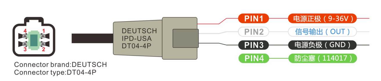
2. Electrical Connection:
Deutch 4-pin connector, model DT04-4P;

3. Dimensions
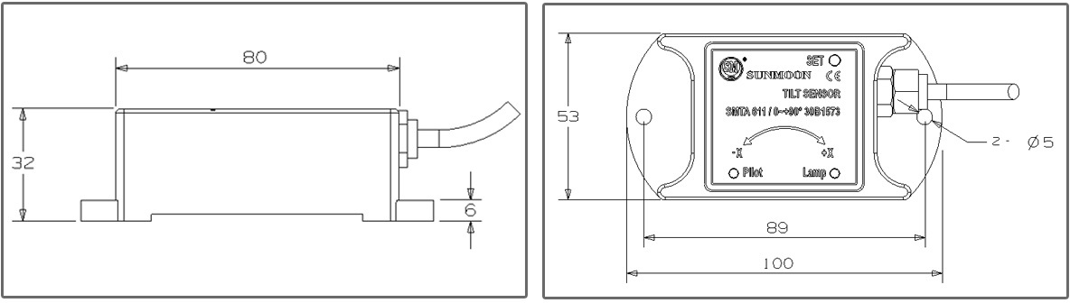
II. SMTA611-A Tilt Switch:
This series of tilt switches are used to measure changes in biaxial tilt angle. When the measured object's tilt angle is less than the preset alarm angle, the tilt switch outputs a high voltage signal equal to the supply voltage; when the measured object's tilt angle exceeds the preset alarm angle, the tilt switch outputs a low voltage signal approximately equal to 0V. The zero-setting button is used to set the horizontal zero point.
1. Technical Specifications:
|
Supply Voltage |
24 (9~36) VDC |
Sensitivity |
3% |
|
Operating Current |
30 mA |
Resolution |
0.1 ° |
|
Measurement Axis |
X, Y Biaxial |
Measurement Accuracy |
±0.1° |
|
Measurement Range |
-30°~+30° |
Operating Time |
80000~100000Hr |
|
Output Signal |
Switch Quantity |
Operating Temperature |
-30℃~ 85 ℃ |
|
Alarm Angle |
X: ±1.5° Y: ±3° |
Storage Temperature |
-40℃~85℃ |
|
Product Certification |
CE Certification |
Response Frequency |
2s |
|
Protection Level |
IP67 |
Vibration Resistance |
>3500 g |
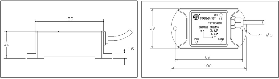
2. Dimensions
3. Electrical Connection
Deutch 4-pin connector, model DT04-4P;
4. Product Installation Direction
During installation, ensure that the mounting surface of the angle switch is parallel to the surface of the measured object, and minimize the impact of dynamics and acceleration on the angle switch.
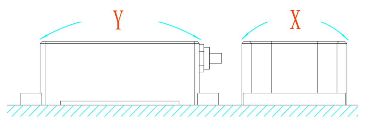
Installation Diagram
5. Instructions for Use
1. Zero Setting Button (Setting Relative Horizontal Zero Point)
The zero setting button is a hidden button located under the PVC panel;
Operation method: Press and hold the zero setting button for 7 seconds. The Pilot indicator light will flash 3 times (red), indicating successful zero setting.
2. Lamp Light
The Lamp light is the power indicator light. This light will always be on (green) as long as the angle switch sensor is powered on.
3. Pilot Indicator Light (Red)
This indicator light has two functions:
A: Successful zero setting prompt (flashes 3 times);
B: When the angle of the measured surface exceeds the set warning angle, the angle switch sensor starts to alarm and outputs a low voltage signal, approximately zero volts. When alarming, the Pilot indicator light continuously flashes (red).
When the power is off or the alarm is cleared, the Pilot indicator light stops flashing and returns to normal operation.
Details
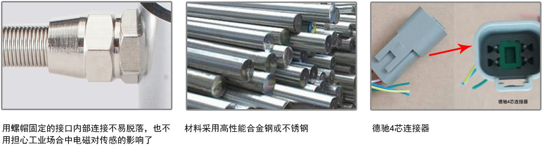
Compact size | Waterproof and dustproof design | Good conductivity
Keywords:
Next
Related Applications

undefined

日月仪器
Contact Fax:0552-4070672
Company Website:www.sunmoon-china.com
Email:smsales@163.com
Address: No. 985, Xingzhong Road, High-tech Zone, Bengbu City, Anhui Province, China, Sun Moon Science and Technology Park
Made in China
