
 Language
Products
PRODUCT CENTER

Cellular network wireless temperature and pressure integrated transmitter SM39PTWB
Oilfield oil pipeline pressure, normally stopped well formation pressure, pressure monitoring and upper and lower limit alarm;
Explosion-proof design: explosion-proof aluminum shell, intrinsically safe circuit board system;
Protection level: IP68, fully sealed waterproof design;
The instrument can set alarm enable, upper and lower limits, delay, dead zone, maximum range, minimum range, decimal places, upload frequency, acquisition frequency, change amount alarm, and other parameters.
LED indication: reset indication, configuration mode indication, networking indication, data acquisition indication;
4 1/2 digit LCD display: pressure data, battery capacity icon, upper and lower limit alarm, and other parameters.
Adjustable installation direction: It can be connected to the on-site pipeline valve through a live connection or a connector, and the direction can be adjusted.
1. Features
- Oilfield oil pipeline pressure, normally stopped well formation pressure, pressure monitoring and upper and lower limit alarm;
- Explosion-proof design: explosion-proof aluminum shell, intrinsically safe circuit board system;
- Protection level: IP68, fully sealed waterproof design;
- The instrument can set alarm enable, upper and lower limits, delay, dead zone, maximum range, minimum range, decimal places, upload frequency, acquisition frequency, change amount alarm, and other parameters.
- LED Indication: reset indication, configuration mode indication, networking indication, data acquisition indication;
- 4 1.5-inch LCD display: pressure data, battery capacity icon, upper and lower limit alarm, and other parameters.
- Adjustable installation direction: It can be connected to on-site pipeline valves through a live connection or adapter, and the direction can be adjusted.
2. Performance indicators
- Operating ambient temperature, -40~70℃,
- Ambient humidity: 0~95%RH, no condensation;
- Protection level: IP68;
- Explosion-proof mark: Ex ib II C T4 Gb,Explosion-proof certificate: CE18.2230X;
- Power supply: ER34615 lithium thionyl chloride battery (implementation standard: SJ52278/1), two primary batteries in parallel, capacity 3.6V 38Ah; battery connector SM-2P (female head: 1 positive pole, 2 negative pole) connected to the instrument; power supply voltage range, 3.0V~3.6VDC;
- Battery continuous working time: ≥1 year (pressure acquisition frequency 1 time/min, communication frequency 1 time/h);
- Battery replacement method: Open the instrument back cover and quickly replace it through the standard SM-2P interface;
- Long-term stability: drift, ±0.1%FS/year;
- Measurement performance: range, 0 ~2.5MPa、0~6.0MPa、0~25MPa、0~40MPa、0~60MPa、; accuracy, 0.5%F.S; can be customized according to actual needs; Complies with GB/T 28474.1 and GB/T 28474.2 regulations;
- Temperature and pressure sensor: Using piezoresistive core & PT100 platinum resistance packaging, overload capacity, 150%FS;
- Process connection interface: M20X1.5 or 1/2’’NPT, can be customized according to actual needs ;
- Communication method: 4G (full network access, compatible with 3G/2G);
- Communication protocol: Complies with the "Cellular Network Temperature and Pressure Transmitter Communication Protocol" to achieve access to the oilfield DMZ server;
- Online debugging and setting functions: It can be debugged and set through the instrument panel or configuration serial port and computer without uninstalling during online installation; the setting data content includes:
- Remote communication parameters: server IP address, port number;
- Measurement parameters: alarm enable, upper and lower limits, delay, dead zone, maximum range, minimum range, decimal places, upload frequency, acquisition frequency, change amount alarm;
After the instrument is powered off, the setting data is retained;
- Online upgrade: It can be realized through the configuration serial port and computer operation without uninstalling during installation;
- Liquid crystal (LCD) display: The liquid crystal display area is 45×35mm in length × width, the background color is green, and the display content includes real-time measured value, pressure unit, instrument range, battery power, voltage, and signal strength; the decimal point of the real-time measured value can be set, and the default is to retain 2 decimal places after the decimal point;
- Instrument shell: The material is aluminum alloy, the shell sealing ring (pad) is silicone rubber, and the front and rear cover threads are coated with Vaseline; the dial diameter is 60mm, and the appearance color number is RAL5007;
- Dimensions: Length × width × height = 150 × 130 × 235mm (MAX).
- Sampling interval: The acquisition interval is 1~60 minutes, which can be set.
- Sending interval: 5~1440 minutes can be set.
Explosion-proof certification parameters
- Explosion-proof certificate number : CE18.2230X
- Explosion-proof mark: Ex ib ⅡC T4 Gb
- Appearance structure and function introduction
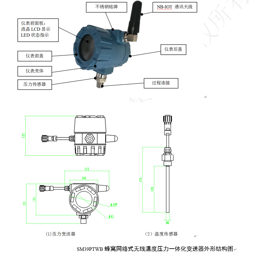
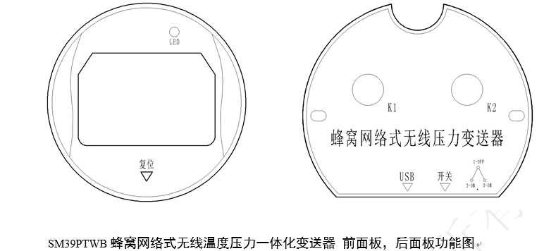
Front panel LED: There are two colors, red and green. Red indicates the pressure acquisition status and the sleep-to-wake-up status. The green LED indicates the NB-IOT network connection status.
Front panel reset: Use a magnet, located below the front cover of the housing. Hold the magnet against the reset arrow for 3-5 seconds, then remove it. The red LED will flash three times, and the LCD display will also display 8888 and flash three times simultaneously, indicating that the instrument has been successfully reset. The main purpose of the reset is to enter the instrument to modify internal parameters, or to refresh the current pressure value and re-establish the network connection.
After opening the instrument back cover, there are batteries, buttons, switches, and USB debugging ports inside the back cover. The functions are described as follows:
Rear panel K1: Because the instrument reporting cycle has a long cycle, during the debugging process, you can press the K1 button, and the instrument will actively establish a network connection and report a set of current pressure data. K1 is mainly used to debug whether the network is in normal use.
Rear panel K2: Because the instrument reporting cycle has a long cycle, some application sites need to observe the real-time number of the current pressure. During the debugging process, you can press the K2 button, and the instrument will actively continuously collect the current pressure for 300 seconds, and the LCD will be refreshed in real time. This function only collects data on site and does not upload it. K2 is mainly used for on-site pressure debugging.
Rear panel switch: The switch is divided into three positions: upper, middle, and lower. The middle position is in the off state, and the upper and lower positions are in the on state.
Rear Panel USB: USB + debugging software allows for convenient input of IP address, network number, and other debugging parameters. See the debugging software manual for details.
Rear Panel Battery Replacement: First, turn off the power switch. Remove the two M3 knurled screws on the left and right sides by hand. Then, vertically remove the K1-K2 circuit board cover. Disconnect the black SM plug of the battery. Replace the battery with a new one, reinsert the SM plug, gently reinsert the K1-K2 circuit board vertically into the pins, and finally tighten the two M3 knurled screws by hand. Turn on the switch. During the entire process, note that the K1-K2 circuit board should be gently inserted and removed. Finally, tighten the rear cover. The physical photo is shown below:
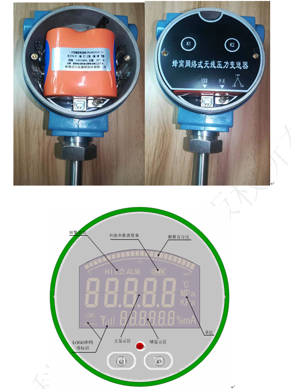
Alarm Status
When an alarm occurs, it is displayed (upper and lower limit alarms are not displayed simultaneously). Only the main display area shows the alarm status of the physical quantity.
Battery Level
Displays the battery voltage according to the battery level.
Measurement Percentage
Percentage of the measured value relative to the full scale.
LOGO and Network Indicator
LOGO Always displayed. The network indicator shows the actual network status.
Main Display Area
Used to display the current value of the physical quantity, pressure or temperature, with unit symbol at the end.
Auxiliary Display Area
Used to display auxiliary information, such as unit logo, NB-IOT signal network indicator, battery voltage, etc.
Unit
Displayed according to instrument type requirements. Mpa, Kpa, and ℃ units can be set.
On-site Installation and Usage Instructions
5.1. All transmitters have undergone digital calibration, and different transmitters have complete consistency and interchangeability.
5.2. During transportation, the batteries of all transmitters are in the disconnected state. When installing the pressure transmitter on-site, you need to unscrew the meter head cover and turn on the battery switch. Be sure to tighten the protective cover to prevent water leakage.
5.3. For installing the cellular network wireless temperature and pressure integrated transmitter on pipelines and shut-in wells, first close the valve (needle valve or gate valve) on the pipeline where the pressure transmitter is to be installed. There are two installation methods: (1) Screw the pressure transmitter directly into the upper port of the needle valve; (2) Screw the union or adapter into the upper port of the needle valve, and then screw the transmitter into the upper port of the union or adapter. This installation method uses a union or adapter to adjust the direction. After installation, open the needle valve to confirm that there is no leakage, indicating that the installation is qualified.
Installing the Temperature Probe on the Pipeline (1) Pipeline shutdown, depressurization, and evacuation. Drill a hole on the pipeline slightly larger than the outer diameter of the sensor probe's blind pipe sleeve; (2) Vertically insert the blind pipe sleeve from the hole to the bottom of the pipeline, and then weld it to the pipeline around the hole; (3) Inject heat transfer oil into the blind pipe sleeve, approximately 1/2 the volume of the pipe; (4) Insert the temperature sensor probe into the blind pipe sleeve, adjust the direction of the meter head, and tighten the union with a wrench to restore pipeline transportation.
5.4. Connect the temperature sensor and the pressure transmitter's cable with a waterproof connector and socket, and then you can perform pressure and temperature tests. After installing this cellular network wireless temperature and pressure integrated transmitter, you can set the network parameters using buttons or debugging tools.
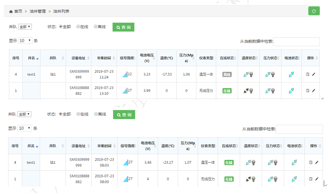
5.5. If the transmitter is not used for a long time, you can set the pressure transmitter to sleep mode using the debugging tool (during the factory warehousing process, it is uniformly set to sleep mode or off state; it needs to be activated on-site to be used normally ). The online list of the debugging software interface is shown below:
6. Precautions
6.1. The battery model used in this product is ER34615M-3.6V38Ah; do not use other battery models.
6.2. The product antenna housing is made of plastic and has a potential electrostatic charge hazard! Avoid friction during use! Please wipe with a damp cloth when cleaning!
Keywords:
Related Applications

undefined

日月仪器
Contact Fax:0552-4070672
Company Website:www.sunmoon-china.com
Email:smsales@163.com
Address: No. 985, Xingzhong Road, High-tech Zone, Bengbu City, Anhui Province, China, Sun Moon Science and Technology Park
Made in China
