
 Language
Products
PRODUCT CENTER

Customized load sensor
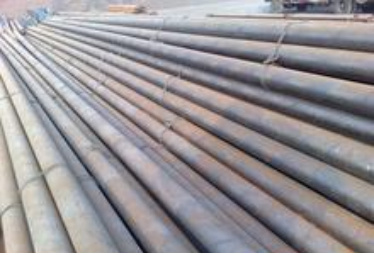
The load sensor is designed for sucker rod pump well work diagram testing. It is a load sensor with high anti-interference performance. The product adopts standard mv signal output or AD amplifier board voltage signal output 0.1-1.5V/0.1-2.5V and fully sealed design, can work in high temperature, high cold, high humidity, high radiation and other harsh environments, and is currently widely used in sucker rod pump work diagram measurement systems.
Overview
The load sensor is designed for pump jack well work diagram testing. It is a load sensor with high anti-interference performance. The product adopts standard mv signal output or AD amplifier board voltage signal output 0.1-1.5V/0.1-2.5V and full sealing design, can work in high temperature, high cold, high humidity, high radiation and other harsh environments, is currently widely used in pump jack work diagram measurement system.
The high reliability design suitable for industrial environment, as well as high precision, easy installation, easy maintenance, environmental protection and durability, has won user recognition, not only in China's Shengli, Daqing, North China, Changqing, Xinjiang, Qinghai and other major oil fields are widely used, but also in overseas oil companies have been partially applied.
Features
Active installation, saving installation and crane costs;
Fully sealed waterproof design, suitable for all-weather use;
High reliability;
Easy and safe operation;
Can be used with other types of wireless data transmission fixed load/displacement
Transmitter to form a wireless testing system;
Consistent output, fully interchangeable.
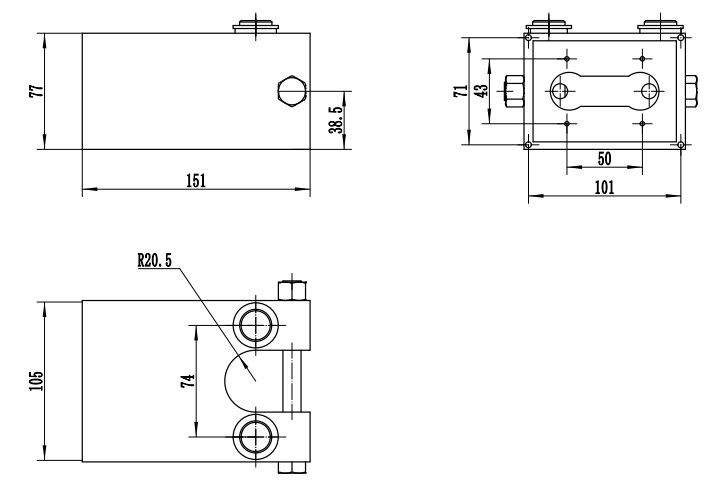
Dimensions (In mm. 1mm=0.03937 inches)
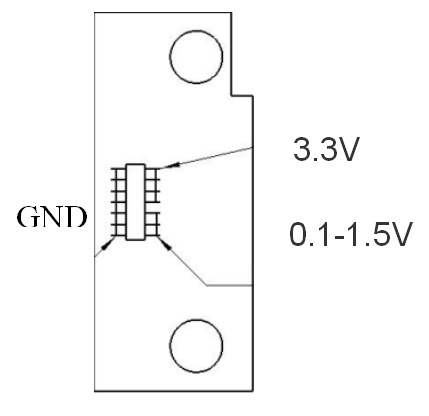
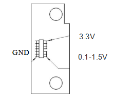
Circuit Diagram:
|
Red: |
input |
Red: |
Power supply |
|
Blue/White: |
GND |
Blue/White: |
Common terminal |
|
Yellow: |
output |
Yellow: |
Signal |
Specification
|
Item Type |
Technical parameters |
|
Measuring range |
0~150 KN |
|
Output |
0.1-1.5V |
|
Overall accuracy |
0.5%FS |
|
Insulation resistance |
≥5000MΩ |
|
Zero output |
≤0.1%FS |
|
Operating voltage |
3.3 VDC |
|
Temperature drift |
0.5%FS/10℃ |
|
Temperature compensation |
-10~65℃ |
|
Operating temperature |
-40~+85℃ |
|
Safe overload |
150% FS |
|
Yield strength |
300% FS |
|
Material |
High-performance alloy steel or (chromium ratio>15% stainless steel) |
|
Protection level |
IP68 (IEC60529) |
Express code
| 110235YD013f | 150KN | φ40 |
| 250KN | φ40 |
Keywords: unloading load sensor for pump jack well testing, U-shaped load sensor, wired load sensor, load indicator
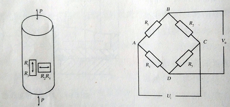
Working principle
The load sensor mainly uses the elastic deformation of the columnar elastic body under the action of external force, so that the resistance value of the strain gauge pasted on its surface changes (increases or decreases), and then converts this resistance change into an electrical signal (voltage or current) through the corresponding measuring circuit, thus completing the testing process.
Details
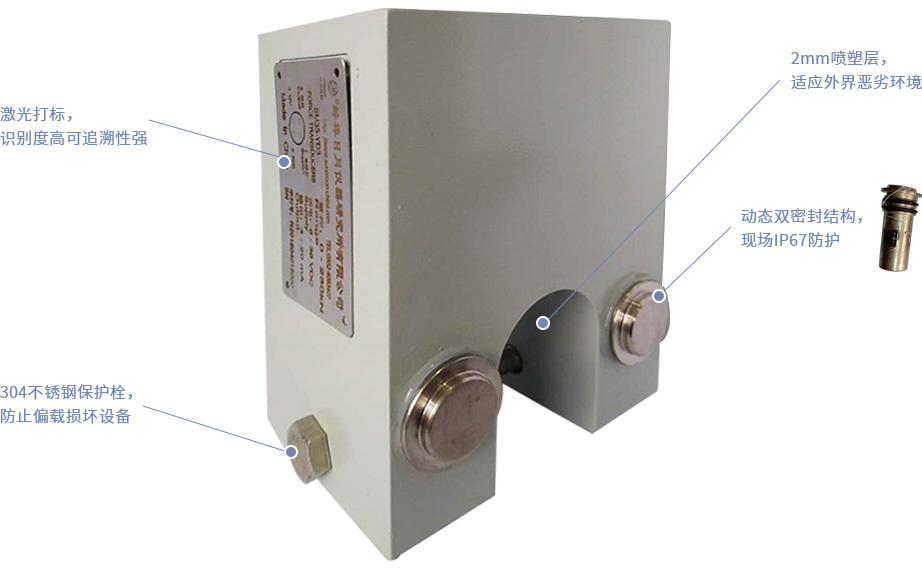
Excellent alloy steel material
Using high-quality alloy steel, after quenching, the hardness is high. The nickel-plated anticorrosion layer has good corrosion resistance and can maintain long-term stability in harsh external environments.
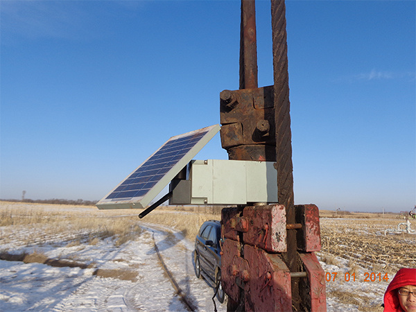
Application scenarios
Usage and precautions:
(1) When determining the sensor specifications, it is recommended to select 80% of the rated load.
(2) When designing the loading device, the user should ensure that the line of action of the loading force coincides with the force axis of the sensor to avoid measurement errors caused by lateral force.
(3) Sensor cable wiring markings:
A: Sensor: Power supply +: Red, Power supply -: Blue
Signal +: Yellow, Signal -: White
B: Amplifier: Power supply: Red, Common terminal: White (blue)
Signal: Yellow
(4) After the sensor is connected to the power supply and starts working, it must be preheated, and the instrument must be stable before starting work. When performing long-distance measurements, the grounding wire shield must be grounded after being connected to the system.
(5) The sensor housing, protective cover plate, and lead connector are all sealed. Please do not open them arbitrarily.
(6) The sensor storage environment should be dry and free of corrosion. Avoid using the sensor near high non-working heat sources.
Keywords:
Previous
Next
Related Applications

undefined

日月仪器
Contact Fax:0552-4070672
Company Website:www.sunmoon-china.com
Email:smsales@163.com
Address: No. 985, Xingzhong Road, High-tech Zone, Bengbu City, Anhui Province, China, Sun Moon Science and Technology Park
Made in China
