
 Language
Products
PRODUCT CENTER

Explosion-proof digital pressure and temperature transmitter SM39PTCRD
Pipeline pressure testing has been widely used in major oil and gas fields and other industrial pressure testing fields across the country; explosion-proof and fully sealed waterproof design; synchronous acquisition of pressure and temperature signals and output via RS485; 3.6VDC backup battery to meet on-site power failure display function;
1. Features
- Pipeline pressure testing, widely used in major oil and gas fields and other industrial pressure testing fields nationwide;
- Explosion-proof, fully sealed waterproof design;
- Simultaneously collects pressure and temperature signals and outputs them via RS485,
- 3.6VDC Backup battery, can meet the on-site power failure display function;
2. Technical Indicators
- Operating environment: Temperature, -40℃≤Tamb≤+65℃; Pressure: 80KPa~110kPa; Humidity: 5%RH~95%RH
- Power supply: 24VDC
- Sensor type: Piezoresistive
- Output signal: RS485-MODBUS RTU protocol; 4 1/2 digit LCD display.
- Housing material: Cast aluminum, Protection level: IP65
- Sensor material: 316L stainless steel
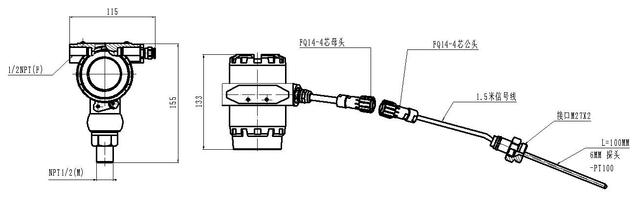
- Electrical connection: NPT1/2″(F) internal thread
- Process connection: NPT1/2″(M) external thread
- Range: 0~0.16、0.4、0.6、1.0、1.6、2.5、4、6、10、16、25、40、60MPa, etc. (customizable), Accuracy grade: 0.5.
- Dimensions: Height 155 × Width 115 × Depth 133; Weight: Approx. 1kg
- Explosion-proof certification: Explosion-proof certificate number: CE13.1219 Explosion-proof mark: EXd IIc T6 Gb
3. Dimensional drawing
3. Installation and commissioning instructions and wiring definitions
3.1. All transmitters have undergone digital calibration, and different transmitters have complete consistency and interchangeability;
3.2. For on-site installation of pressure transmitters, unscrew the head cover, connect the cable to the electrical interface, connect the 485 communication line and the backup battery line. During the connection process, please pay attention to the correct connection of the positive and negative power supply. Finally, tighten the cover to ensure waterproofing.
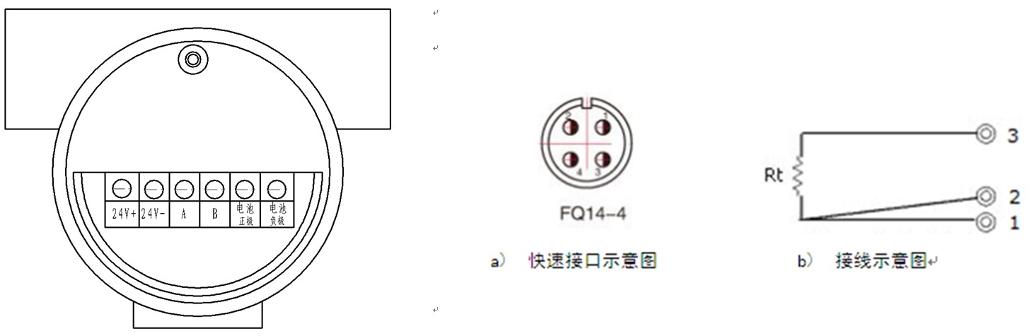
3.3. The six-core wiring terminal is defined from left to right as follows:
1- 24V+ power supply, 2- 24V- power supply, 3- 485_A, 4- 485_B, 5- Battery positive, 6- Battery negative,
3.4. Temperature probe three-wire wiring definition:
1-PT100 Signal-, 2- PT100 signal-, 3- PT100 signal+
 3.5 Display panel indication definition
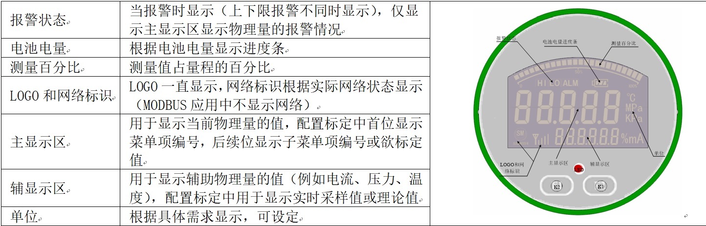
Under the default settings, after the instrument is powered on, it works in the loop current state. The main display area displays the current pressure value and temperature value alternately. The battery progress bar only displays the battery power when there is no external power supply.
3.6 On-site setting of instrument communication basic information
As shown in the figure below, the instrument communication address is the factory default 01 On-site users can set it. Use the debugging software "Digital Pressure Transmitter Debugging Software", in the device communication basic information status bar under the intelligent sensor general information status, first fill in the universal address in the instrument communication address SMD03 Digital Pressure Transmitter 485 Debugging software", in the device communication basic information status bar under the intelligent sensor general information status, first fill in the universal address in the instrument communication address 255 then "Read", after successful communication, other setting codes will be displayed, and the instrument communication address can be set and recorded. The baud rate is the default 9600 , the serial port is the serial port number of the current computer, generally com1, com2, The specific serial port number of the current computer can be found in the Device Manager.
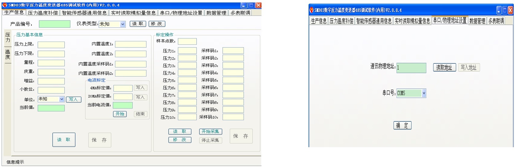
3.7 Pressure transmitter parameter setting
As shown in the figure below, the pressure range can be read but not set by the user, and the pressure decimal places can be selected 0-2 bits. Tare weight, is the instrument unloaded to zero, but will not modify the factory calibration gain of the transmitter. When the transmitter is used for a period of time, regular calibration and zeroing, the transmitter can be suspended, when the transmitter display value is not zero, the tare weight can be set to the display value, that is, zeroing. For example: the on-site instrument displays unloaded 0.5MPa, The tare weight can be set to 0.5 , and the transmitter output subtracts the corresponding signal value of the tare weight.
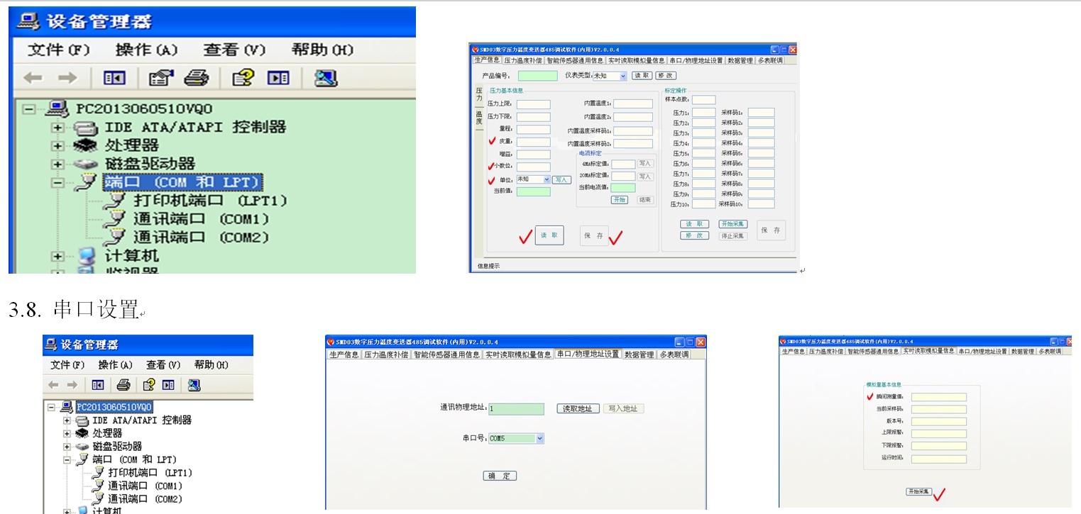
According to the computer configuration and the actual connected computer serial port, select COM1 or COM2。
3.9. Real-time reading of analog information
Fill in the instrument communication address, click start reading, the instantaneous measured value will be refreshed in real time, which can be used for on-site debugging. The basic information here (instantaneous measured value, current sampling code, version number, upper limit alarm, lower limit alarm, running time) can only be seen, but cannot be modified.
Keywords:
Related Applications

undefined

日月仪器
Contact Fax:0552-4070672
Company Website:www.sunmoon-china.com
Email:smsales@163.com
Address: No. 985, Xingzhong Road, High-tech Zone, Bengbu City, Anhui Province, China, Sun Moon Science and Technology Park
Made in China
