
 Language
Solutions
Application Solution
Oilfield testing instrument application/oil well indicator diagram and liquid level testing system solution
Category:
Oil and gas Internet of Things (IoT) solutions
Publish Time:
2021-10-14
1. Overview
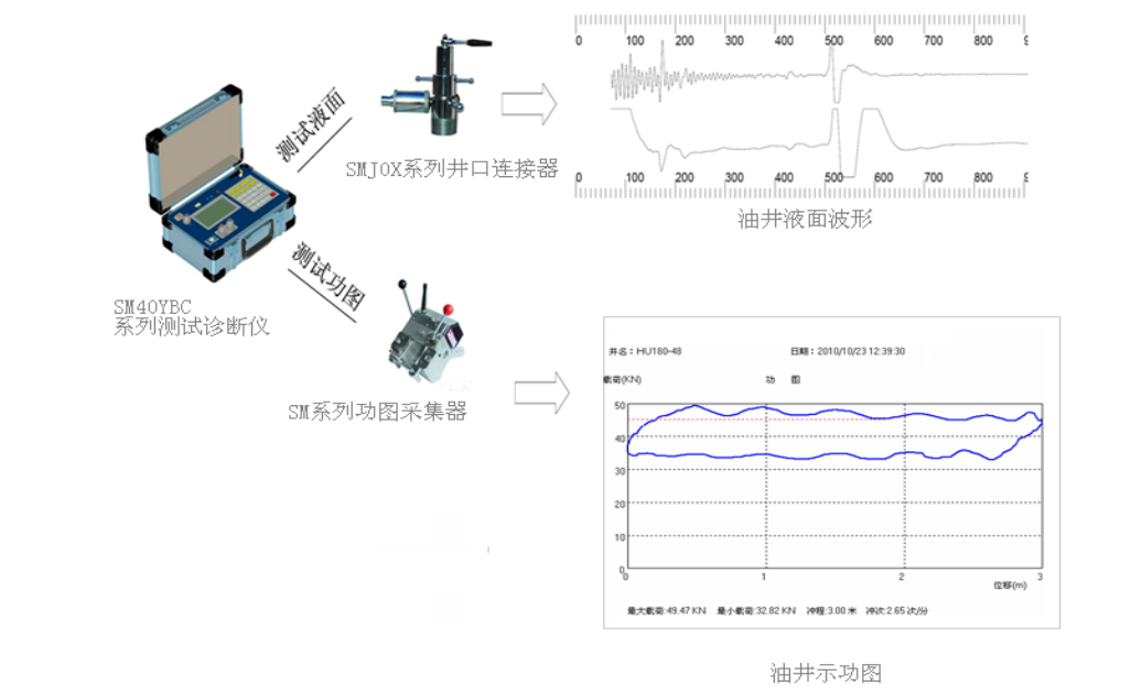
The oil well indicator diagram and liquid level testing system based on portable instrument applications consists of three units: a wireless portable testing and diagnostic instrument, a wireless digital indicator diagram collector, and a wellhead connector.
The testing and diagnostic instrument and the indicator diagram collector combine to form an indicator diagram testing system. The wireless digital indicator diagram collector collects the oil well indicator diagram and transmits the data wirelessly to the testing and diagnostic instrument. The testing and diagnostic instrument and the wellhead connector combine to form a liquid level testing system. The wellhead connector collects the liquid level data and transmits the data wired to the testing and diagnostic instrument.
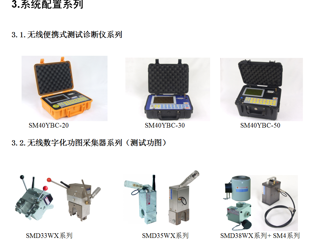
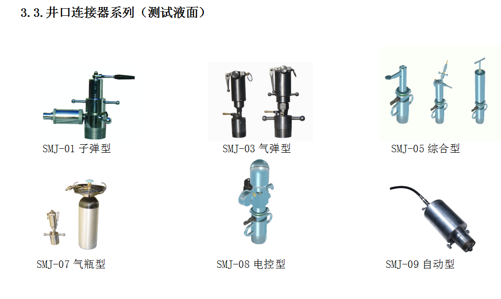
Currently, our company produces SM40YBC series instruments, compatible with both "indicator diagram" and "liquid level" functions. They are equipped with SMJ0X series wellhead connectors, SMD33WX, SMD35WX, SMD38WX, SM4, and other series indicator diagram collectors to form the system solution. This system has been used in many oilfields in China and is basic equipment for oil well diagnosis in oilfield units.
2. Features
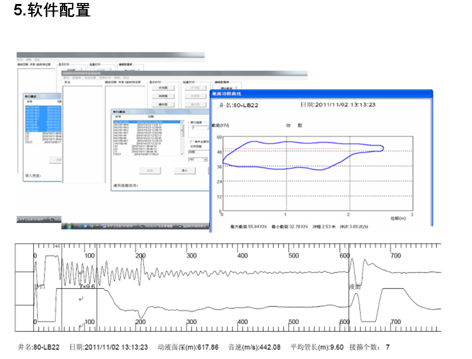
Wireless indicator diagram acquisition, suitable for oil wells with different strokes; original imported military-grade industrial computer; modular design; hanging structure; fully sealed keyboard; suitable for field work; simple and practical testing; can store more than 1000 well indicator diagram data; continuous operation time up to 10 hours.
Wired dynamic liquid level acquisition, compatible with multiple wellhead connectors to meet different well conditions; the dynamic liquid level acquisition waveform is clear, the repeatability is stable, and the testing accuracy is high.
4. Technical Indicators
2.1. Load: 0 ~ 90, 120, 150 kN 0.5%F.S ;
2.2. Displacement: 0 ~ 8 m, 0.5%F.S ;
2.3. Dynamic Liquid Level: 0 ~ 3000m 0.5% F.S。
6. System Configuration
Table 1. SM40YBC-20 Oilfield Indicator Diagram and Liquid Level Integrated Testing System Configuration
| Serial Number |
Name |
Model Number |
Quantity |
Function |
| 1. |
Wireless Portable Testing and Diagnostic Instrument |
SM40YBC-20 |
1 Unit |
Testing and Diagnostic Device |
| 2. |
Cylinder Type Wellhead Connector |
SMJ-07 |
1 Unit |
Liquid Level Measurement Device |
| 3. |
Wireless Digital Hydraulic Load and Displacement Integrated Sensor |
SMD33WX |
1 Unit |
Indicator Diagram Measurement Device 1. |
| 4 |
Wireless Digital Load and Displacement Integrated Sensor |
SMD35WX |
1 Unit |
Indicator Diagram Measurement Device 2. |
| 5 |
Wireless Digital Displacement Transmitter |
SMD38WX |
1 Set |
Indicator Diagram Measurement Device 3. |
| 6 |
Load Sensor |
SM4 |
Note: The system configuration can refer to " 3. System Configuration Series" for free selection.
Our company has been wholeheartedly serving the oilfield testing industry for many years. We are professional developers and manufacturers of complete sets of sensors, RTUs, oilfield instruments, and measurement and control software, as well as providers of complete testing solutions. We not only provide a complete series of remote monitoring and control solutions for oil wells, but also provide a complete series of indicator diagrams, system efficiency, wellhead liquid level, screw pump torque load speed, and other testing and diagnostic instruments. These can be used as standard tools for comparison and calibration of various parameters in oil well remote monitoring and control, or they can be used independently for testing. Remote monitoring and control and instrument testing complement each other to jointly build China's digital oilfield!
Keywords: Wireless portable testing and diagnostic instrument, wireless digital power graph collector, wellhead connector, testing and diagnostic instrument, power graph collector, oil well power graph liquid level testing system
Next:

日月仪器
Contact Fax:0552-4070672
Company Website:www.sunmoon-china.com
Email:smsales@163.com
Address: No. 985, Xingzhong Road, High-tech Zone, Bengbu City, Anhui Province, China, Sun Moon Science and Technology Park
Made in China
