
 Language
Solutions
Application Solution
Digitalized inter-valve group measurement and control scheme for Changqing Oilfield cluster wells
Category:
Oil and gas Internet of Things (IoT) solutions
Publish Time:
2021-10-14
Traditional data acquisition scheme for valve groups in Changqing Oilfield cluster wells is to treat multiple flow meters and pressure transmitters as Modbus devices and collect data on the software ,there are serious shortcomings: ( 1 ) The software needs to one by one instrument for polling acquisition, unable to collect all at once , Communication efficiency is inevitably low, the cycle is longer, single well data acquisition will also be affected; ( 2 )Changqing actual field conditions are not , valve groups use flow meters and pressure transmitters from different manufacturers , protocols vary ,development and maintenance are difficult. In view of this, this scheme integrates and merges the valve group control in the measurement and control structure of Changqing Oilfield cluster wells, thus forming a complete set of measurement and control for the cluster well field, and effectively solves the above problems.
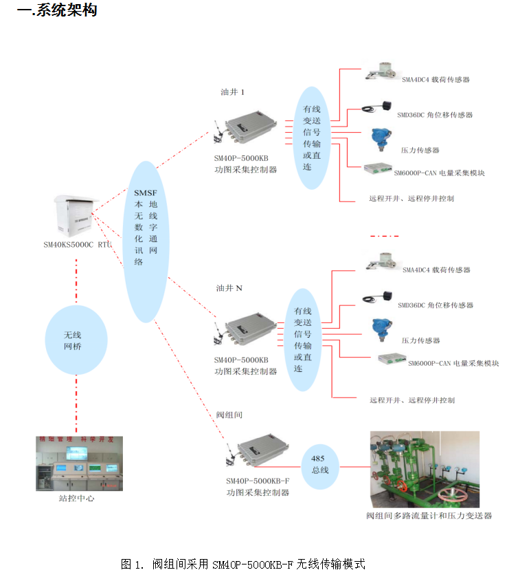
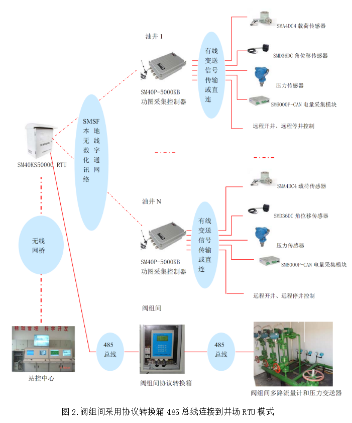
Well site RTU through RS485(Modbus RTU ,valve group protocol converter ) or local wireless ( SM40P-5000KB-F valve group collector) with the water injection valve group group communication, real-time acquisition water divider pressure, water injection well pressure, instantaneous flow, cumulative flow and other real-time parameters, and through remote water injection and distribution control ,to achieve the function of water injection according to the plan and the actual flow demand at the wellhead. SM40P-5000KB-F Valve group collector ,plays a universal wireless protocol converter, integrating 1 path RS485 and local wireless 。1 path RS485 can access RS485 flow meters or pressure transmitters with signals , The software supports various standard communication protocols or custom protocols. It is compatible with instruments and equipment from various manufacturers, bringing many conveniences to equipment maintenance and later modifications ; local wireless can realize wireless uploading of valve group data to the well site RTU 。
SM40P-5000KB-F Valve group collector Collect and summarize the instrument data of the valve group. After unifying the data format, upload it centrally at one time. On the one hand, it can improve communication efficiency and avoid the upper computer polling the valve group instruments one by one, resulting in a long polling cycle. On the other hand, it unifies the data interface with the upper computer, which is convenient for the development, debugging and maintenance of the upper computer software.
1. Three-level link communication
1.1. Valve group data acquisition: Install the protocol conversion box to measure the data and transmit it to the RTU via the RS485 bus, or install the SM40P-5000KB-F valve group collector to measure the data and transmit it wirelessly to the RTU. Valve group data: water injection pressure of each well, instantaneous water injection flow, cumulative flow, water divider pressure, etc.
1.2. Well site data acquisition: The RTU collects the valve group data and uploads it to the station control center, and can also control the collector or protocol box to remotely allocate the water injection flow, etc.
1.3. Station control data acquisition: The station control center remotely controls the RTU. According to the settings, data is collected, stored and reports are generated, and the water injection flow can also be remotely allocated.
2. Communication index
2.1. Figure 1 mode, local wireless digital network communication: Line of sight ≥300m. Carrier frequency: 433MHz, belongs to ISM working frequency band, no frequency point application is required. GFSK narrowband modulation, and efficient forward error correction channel coding and decoding technology is adopted to improve the reliability of data communication under low power consumption. The local wireless network can be used for wireless communication between the well site valve group and the collector of the oil pump and the RTU.
2.2. Figure 2 mode, bus communication: RTU extended data communication RS485, 1 channel, can connect third-party devices through standard Modbus or custom protocols. For example, it connects to third-party protocol boxes in valve group measurement applications.
2.3. RTU remote communication: Ethernet interface, 10BASE-T PHY ,compatible 100/1000 BASE-T network.
two . Implementation plan
1. Well site monitoring
As can be seen from the above system architecture, this system uses RTU as the data intermediary, and the valve group, well site, and station control form a three-level hierarchical monitoring network. For RTU, distance radius 300 meters The well group within can be regarded as a well site.
1.1. Inter-valve group monitoring: Install a protocol box to collect data and upload it to the RTU via a 485 bus, or install an SM40P-5000KB-F type inter-valve group collector to collect data and wirelessly transmit it to the well site RTU.
1.2. Well site monitoring: Install one RTU at each well site to monitor the inter-valve group data and pumping unit data.
2. Inter-valve group configuration
| Serial Number |
Name |
Model |
Specification |
Quantity |
Purpose |
|
| 1 |
Intelligent oil well monitoring terminal |
SM40P-5000E-II-E |
|
1 unit/well site |
Well site data acquisition and remote communication. |
|
| Water injection inter-valve group (1 unit) |
||||||
| 1 |
Pressure sensor |
|
RS485 communication |
Several |
User-provided |
|
| 2 |
Flow meter |
|
RS485 communication |
Several |
User-provided |
|
| 3 |
Valve group collector |
SM40P-5000KB-F |
Wireless transmission |
1 set |
Data terminal acquisition, choose one of the two. |
|
| Loop protocol converter |
|
RS485 communication |
1 set |
|||
III. SM40P-5000KB-F type inter-valve group collector:
1 Measurement function
1.1. Node capacity: Each RS485 interface device (flow meter or water divider pressure gauge, etc.) is a single node. This collector can connect 0 ~ 32 nodes. One node monitors the variables of one water well, including pipe pressure, instantaneous flow rate, cumulative flow rate, or monitors the pressure of a water divider.
1.2. Real-time monitoring: The overall pressure of a water divider (manifold) in the inter-valve group and the instantaneous flow rate, cumulative flow rate, and water injection pressure data of each water well;
1.3. Parameter setting: Set the instantaneous flow rate, pressure, valve control, and valve working mode.
1.4. Data storage: Capacity 32KB bytes, by 10 well allocation, acquisition cycle 10 seconds, can save 364 packages (equivalent to 1 hours) of data. Even if the communication is interrupted (not exceeding 1 hour), the data will not be lost to ensure data continuity.
1.5. Wireless communication: The collector and RTU use a local wireless communication network for communication. Installation is convenient and fast, and compared to the traditional inter-valve group 485 bus connection RTU measurement mode, it eliminates the need for digging trenches and laying cables, greatly saving construction costs.
2. Data link platform
Extended data communication interface, RF wireless data communication and main RTU broadband data communication, establishing a communication link platform for well site data equipment 。
3. Technical indicators
3.1. Industrial environment design, outdoor installation, IP65 sealed die-cast aluminum housing.
3.2. EMC suppression capability, IEC61000-4-4 strength level 3.
3.3. Operating temperature, -40℃~+85℃.
3.4. Local wireless digital network communication, as a data communication link interface between RTUs, line of sight ≥300m. Carrier: 433MHz, ISM operating frequency band, no frequency point application required. GFSK narrowband modulation.
3.5. Extended data communication interface: EIA-RS485-A standard, photoelectric isolation, isolation voltage 1000Vdc/1 minute.
3.6. RTC real-time clock, FRM ferroelectric memory, Capacity 32KB bytes . Ensure that data is not lost when communication is interrupted.
3.7. Industrial-grade power supply, EMI/surge filter, compatible with 220V/380V/660V various on-site voltages, directly powered from the pumping unit electrical control box.
Four . On-site installation:
SM40P-5000KB-F The type inter-valve group collector is wall-mounted. Please extend the suction cup antenna vertically and attach it to the top of the inter-valve group room.
V. Solution description:
1. If using SM40P-5000KB-F type inter-valve group collector, with RTU in wireless transmission mode, then on-site trenching, piping, and wiring are eliminated, and the construction cost is extremely low.
2. SM40P-5000KB-F type inter-valve group collector adopts wall-mounted installation, which is convenient and quick to disassemble and install.
3. If the inter-valve group is already installed with protocol box, then you can choose 485 bus connection well site RTU mode, which involves more trouble in trenching and wiring. If there is no protocol box, then only SM40P-5000KB-F type inter-valve group collector can be installed; choose one of the two.
4.SM40P-5000KB-F type inter-valve group collector can be externally connected to CDMA/GPRS/SCDMA and other communication equipment to directly transmit data to the station control center without an intermediary well site RTU Suitable for single-well "one-to-one" remote monitoring.
5. This article mentions the well site RTU Suitable for well site monitoring. For RTU, it is considered distance radius 300 meters The well group within can be regarded as a well site. that is, one RTU manages multiple oil wells and valve groups within a well site, i.e., the "one-to-many" mode. A well site only needs one RTU and one set of communication equipment, resulting in lower overall costs.
Keywords: Wellsite monitoring, wellsite data acquisition, station control data acquisition, oilfield wellsite monitoring system, oilfield oil well acquisition system, subordinate wellsite acquisition system
Return

日月仪器
Contact Fax:0552-4070672
Company Website:www.sunmoon-china.com
Email:smsales@163.com
Address: No. 985, Xingzhong Road, High-tech Zone, Bengbu City, Anhui Province, China, Sun Moon Science and Technology Park
Made in China
