
 Language
Solutions
Application Solution
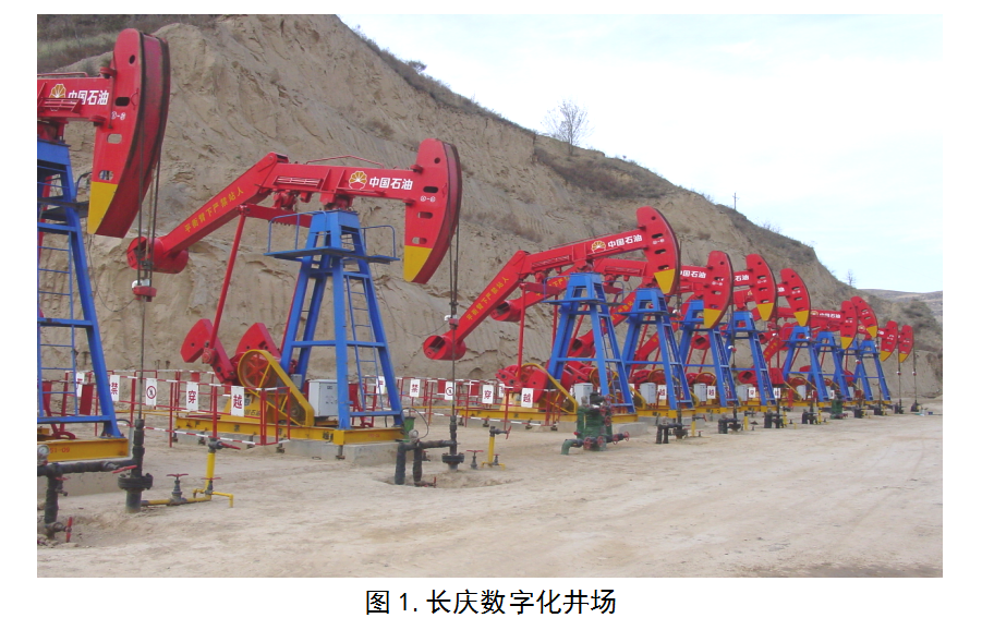
Digital wellsite (group) monitoring solution for Changqing Oilfield model
Category:
Oil and gas Internet of Things (IoT) solutions
Publish Time:
2021-10-14
- System Architecture (Three-level cascading communication link)
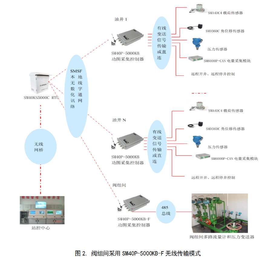
( 1) Single-well data acquisition: The dynamometer chart acquisition controller (hereinafter referred to as the acquisition device) acquires data from oil wells or water injection valve groups in real time. Single-well dynamometer charts, three-phase electricity of the motor, wellhead oil pressure (or manifold pressure), remote control of pump jack start/stop, etc. are acquired; for water injection valve groups, the injection pressure, instantaneous flow rate, cumulative flow rate, and manifold pressure of each water well are acquired.
( 2) Well site data acquisition: The well site RTU manages various acquisition devices at the well site through the SMSF local wireless digital communication network, i.e., manages the data acquisition and control of N oil wells and water injection valve groups at the well site, where N ranges from 1 to 22. The RTU is commanded to acquire well site data and upload it to the station control center, and is also commanded to remotely start/stop the pump jack or adjust the flow rate of the water injection valve groups.
( 3) Station control data acquisition: The station control center remotely manages various well site RTUs through wireless bridges, etc. The RTU connects to the well site switch through an Ethernet interface, the switch connects to the wireless bridge, and the station control center also accesses the data server via a wireless bridge, thus establishing the communication link between the RTU and the station control center. The station control center collects and stores data according to the settings, generates reports, and can also remotely start/stop the pump jack or adjust the flow rate of the water injection valve groups.
2. Implementation Plan
2.1. Well Site Monitoring
As can be seen from the above system architecture, this system uses RTU as an intermediate bridge to implement a three-level cascading monitoring network for single wells, well sites, and station control. For the RTU, distance radius 300 meters within can be considered as a well site.
(1) Single-well monitoring: A dynamometer chart acquisition device and various types of well parameter sensors are installed in each oil well to monitor single-well data, which is uploaded to the well site RTU via the SMSF local wireless method.
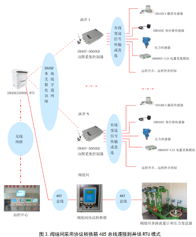
(2) Valve group monitoring: Install a protocol conversion box to measure data and upload it to the RTU via a 485 bus, or install an SM40P-5000KB-F type valve group acquisition device to measure data and upload it to the well site RTU via the SMSF local wireless method.
(3) Well site monitoring: Each well site installs an RTU to monitor all oil wells and water injection valve group data within the well site.
2.2. Well Site Configuration
Table 1. Digital Well Site Configuration
| Serial Number |
Name |
Model |
Specifications |
Quantity |
Purpose |
|
| 1 |
Oil Well Intelligent Monitoring Box |
SM40KS5000E |
|
1 Unit / Well Site |
Well site data acquisition and remote communication. |
|
| Clustered oil wells (several wells) |
||||||
| 2 |
Dynamometer Chart Acquisition Controller |
SM40P-5000KB-II |
|
1 Unit / wells |
Single-well data acquisition |
|
| 3 |
Load Sensor |
SMA4DC-B |
0 ~ 150KN/4 ~ 20mA , two-wire, no polarity |
1 Unit / wells |
Monitor suspension point load; choose one of the two. |
|
| SMA35GDDC-B |
||||||
| 4 |
Angular Displacement Sensor |
SMA3636SC |
-50 ~ 50 ° /4 ~ 20 mA Two-wire, no polarity |
1 Unit / wells |
Monitor suspension point displacement |
|
| 5 |
Pressure Sensor |
SM39Y04 |
0 ~ 4MPa/4 ~ 20 mA |
1 Unit / Well Site |
Monitor manifold pressure; user-provided. |
|
| 7 |
Digital Intelligent Electricity Acquisition Controller |
SM6000P-CAN-ZL |
800VAC/100A |
1 Unit / wells |
Monitor three-phase current, voltage, electricity usage, etc. |
|
| Current Sensor |
SMI-100 |
100A/50 Ma |
3 Unit / wells |
|||
| 8 |
Voice Alarm |
SMBJ01Y |
12V/20W |
1 Unit / wells |
Voice alarm before remote start/stop of well |
|
| Water injection valve group ( 1 sets) |
||||||
| 1 |
Pressure Sensor |
|
RS485 Communication |
Several |
User-provided |
|
| 2 |
Flow Meter |
|
RS485 Communication |
Several |
User-provided |
|
| 3 |
Valve Group Acquisition Device |
SM40P-5000KB-F |
Wireless Transmission |
1 Set |
Data terminal acquisition; choose one of the two. |
|
| Loop Protocol Conversion Box |
User-provided |
RS485 Communication |
1 Set |
|||
|
|
||||||
| 4 |
Day/Night Drive Software |
|
|
1 Set |
Station control center background data processing. |
|
3. Advantages of this Scheme
3.1. Combined with the site, using card-mounted, strong magnetic adsorption installation, advantages:
( 1 ) No open fire, welding, drilling, or earthwork is required, preserving the original appearance of the well site;
( 2 ) Installation, removal, relocation, and moving are convenient and quick;
( 3 ) Installation is safe, firm, and easy to maintain, without affecting well site operations;
3.2. Three-level cascading structure, clear and straightforward, advantages:
( 1 ) Single-well sensors use wired methods: This meets the intensive, reliable, and stable requirements of dynamometer chart acquisition.
( 2 )Data collector and RTU Wireless technology is used: No need for digging trenches, laying pipes, or wiring, saving installation costs.
( 3 )This structure lays the foundation for future digital platform expansion, making expansion convenient.
3.3. Simple and quick debugging. Advantages:
This system is easy to debug, and can be completed in just three steps: well site setup, well site configuration, and system patrol configuration. Generally, installation is equivalent to completion of debugging. Leveraging the advantages of wireless networks, the system can remotely RTU upgrade, configure, detect faults, and maintain the data collector, generally without the need to go to the site.
( 1 )Single-well testing: A Chinese debugging manual is provided. This work is carried out immediately after the installation of a single well on site. Equipped with on-site SM40P-5000K system detection tool, for quick debugging of data collectors, focusing on checking the correctness of installation wiring and the correctness of single-well functions. Short-range wireless detection, no need to connect RTU, no need to open the data collector; simply sit in the on-site duty room or vehicle, open a laptop and connect to a wireless communication terminal to perform the detection, which is convenient and quick. Ensure that the on-site installation and testing are completed once, ensuring a one-time installation pass rate and avoiding repeated trips to the site, saving overall costs.
( 2) Well site testing: A Chinese debugging manual is provided. This work is carried out immediately after the well site RTU installation is completed. For well site RTU quick debugging, focusing on checking the well site RTU system functionality, correctness, and stability. Connect one end of a network cable to RTU and the other end to a laptop. Sit in the on-site duty room or vehicle, open the laptop, and you can perform the detection, which is convenient and quick. Ensure that the on-site installation and testing are completed once, ensuring a one-time installation pass rate and avoiding repeated trips to the site, saving overall costs.
( 3) Station control testing: A Chinese debugging manual is provided. This work is carried out after all well site installations are completed. No detection tools are required. For debugging of the installed well site system, focusing on checking the stability, functionality, and correctness of the entire system communication link. Remote wireless detection; simply sit in the station control center and open your computer to perform the detection, which is convenient and quick. Remote parameter setting, remote software upgrades, and remote functional testing, etc., ensure that the well site RTU testing is completed, ensuring the installation pass rate, without the need to go to the site, saving overall costs.
3.4. Comparison and verification:
We have our own standard instruments, which can be used for data comparison and verification of this system:
( 1 )Convenient detection operation: Using the existing I-beams on the wellhead, the hydraulic sensor is used with the instrument, without the need for load removal, saving time.
( 2 )Convenient and quick comparison: The instrument automatically records the power curve of its own test, synchronously recording the power curve of the data collector. Superimposed on one interface. Automatically displays the comparison graph and parameters. Playback on the computer can generate documents, which can be directly used as a comparison report without further editing.
Keywords: Wellsite monitoring, single-well data acquisition, wellsite data acquisition, station control data acquisition, digital wellsite acquisition system
Previous:

日月仪器
Contact Fax:0552-4070672
Company Website:www.sunmoon-china.com
Email:smsales@163.com
Address: No. 985, Xingzhong Road, High-tech Zone, Bengbu City, Anhui Province, China, Sun Moon Science and Technology Park
Made in China
