
 Language
Products
PRODUCT CENTER
 sensor")
SM35ARD payload displacement (indicator diagram) sensor
The SM35ARD load displacement (indicator diagram) sensor is designed for oilfield pumping unit well indicator diagram testing. It integrates load, acceleration, and displacement measurement functions. Utilizing force-sensitive, acceleration-displacement, RS485 communication, and low-power single-chip microcomputer technologies, it is a new energy-saving digital product. It has obtained multiple patents and passed explosion-proof certification. Designed for industrial environments, it has been applied in major oil fields such as Daqing, Shengli, North China, and Xinjiang, winning consistent praise from users for its high precision, reliability, simple installation, and convenient maintenance.
Description Overview
The SM35ARD load displacement (indicator diagram) sensor is designed for oilfield pumping unit well indicator diagram testing. It integrates load, acceleration, and displacement measurement functions. It uses force-sensitive, acceleration-displacement, RS485 communication, and low-power microcontroller technologies. It is a new energy-saving digital product. It has obtained multiple patents and passed explosion-proof certification. Designed for industrial environments, it has been applied in major oilfields such as Daqing, Shengli, North China, and Xinjiang, winning consistent praise from users for its high precision, reliability, simple installation, and convenient maintenance.
Functions
Table 1. SM35ARD Load Displacement (Indicator Diagram) Sensor Functional Features
|
Item |
Functions |
Advantages |
|
Functions |
Indicator Diagram Acquisition |
Timed (configurable) indicator diagram acquisition; meets the data acquisition needs for indicator diagram oil measurement density points and density time. |
|
Power Supply |
External |
Powered by field instruments or an independent power supply. |
|
Communication |
RS485 Communication |
Requires pipe routing and wiring, saving construction costs; high reliability and strong anti-interference capability. |
|
Power Consumption |
Low-power design |
Sleep/wake-up, event-triggered wake-up automatic switching. |
|
Installation |
U Type open design Anti-drop-off safety design |
Plug-in quick installation, saving installation costs and improving maintenance efficiency. Disassembly and maintenance are convenient, without the need for cranes, etc. |
|
Sealing |
Fully sealed waterproof design |
Meets all-weather use, convenient and safe operation. |
|
Maintenance |
Remote battery voltage monitoring and fault detection, etc. |
Control room remote diagnosis and maintenance, eliminating the need to travel to the site, greatly saving maintenance costs. |
|
Explosion-proof Certification |
Intrinsic safety certification |
Certified by the "Petrochemical Industry Electrical Product Explosion-proof Quality Supervision and Inspection Center". |
Main Technical Indicators
Table 2. SM35ARD Load Displacement (Indicator Diagram) Sensor Main Technical Indicators
|
Item |
Technical Indicators |
Indicator Features |
|
Load |
0 ~150kN, accuracy: 0.5% F.S. |
Can be set as load output mode as needed |
|
Vertical Acceleration Displacement |
Stroke: 1~ 12m , accuracy: 2.0% F.S ; Strokes: Minimum allowed 1 times /min , accuracy: 1 %. |
|
|
Power Supply |
24VDC |
|
|
Dense Acquisition |
Indicator diagram points ≥200, cycle ≥10 minutes (configurable). |
Meets the data acquisition needs for indicator diagram oil measurement density points and density time. |
|
Protection Level |
IP67 |
Dustproof, sandproof, waterproof, etc. |
|
Operating Environment |
-40~+85℃ |
Meets the requirements of industrial environments with high cold and high heat. |
|
Storage Temperature |
-55 ℃~+85℃ |
|
|
Operating Relative Humidity |
5% ~95% non-condensing |
|
|
Communication |
RS485 |
Complies with the A11-GRM communication protocol |
|
Equipment Calibration Cycle |
Recommended 6 months |
|
|
Explosion-proof Certification Parameters |
Explosion-proof mark: Ex ib IIC T4 Gb |
|
|
U Type Opening |
Generally 40mm, customizable. |
Customizable according to the polished rod diameter. |
|
Dimensions |
Length 217 mm × Width 100 mm × Height 66mm |
|
|
Weight |
4.6kg。 |
|
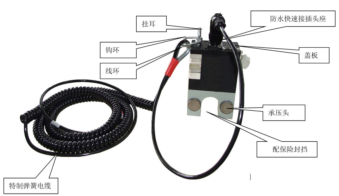
External Structure
Instructions for Use
1. Interchangeability
All load sensors are digitally calibrated, and different load sensors have complete consistency and interchangeability.
2. LED Indication
There is a dual-color (red and green) LED inside the antenna sheath, with definitions as shown in Table 3:
Table 3. SM35ARD Load Displacement Sensor LED Definition
|
Indicator Light |
Status Description |
Definition |
Remarks |
|
Red LED (Mode Indication) |
Bright |
Configuration Mode |
Common parameters, instrument calibration, power curve control parameters, power curve acquisition cycle. |
|
Interval 1 Flashes multiple times per second |
Indicates that regular data is being uploaded |
The sensor periodically sleeps and wakes up, and sends data actively after waking up Regular data to RTU Load sensor regular data includes: instantaneous load value, battery voltage, communication efficiency. |
|
|
Green LED (Power curve measurement) |
Bright |
During power curve measurement |
During this process, red LED Every 1 seconds flash. |
|
Flash |
Power curve measurement complete |
Installation
Installed between the sucker rod pump suspension and the polished rod clamp, The installation direction should be with the pressure head upward and the calibration interface downward, ensuring that the two protruding pressure heads of the sensor are upward and vertically stressed.
Installation steps are as follows:
1. Stop the pump jack about 30cm from the bottom dead center (wellhead) and engage the brake.
2. Clamp the polished rod at the wellhead with a fixed clamp, release the brake, start the pump jack to completely unload the suspension (i.e., the polished rod clamp and suspension are separated), immediately stop the machine, and engage the brake again.
3. Load sensor Loosen the anti-loosening bolt nut and remove the bolt.
4 Between the polished rod clamp and the suspension, or between the upper and lower plates of the suspension, Load sensor U Insert the polished rod into the opening (Note: The installation direction should be with the pressure head downward, ensuring that the pressure head of the sensor is downward and vertically stressed) Insert the anti-loosening bolt into the U hole and lock it, tighten the nut.
5. Straighten the suspension and load sensor , then release the brake , Release and brake, brake and release, control the suspension to rise slowly and load smoothly.
6. Remove the fixed clamp and polish the scratches on the polished rod.
Precautions
1. During installation, The installation direction should be with the pressure head downward, ensuring that the pressure head of the sensor is downward and vertically stressed , do not invert!
2. If any problems occur during the use of the product, please contact us in time. We provide 24 hours of telephone support. Unauthorized opening is strictly prohibited, otherwise, no warranty will be provided.
3. This product is independently developed by our company and has independent intellectual property rights, and has obtained multiple patents. Any unit or individual is strictly prohibited from copying, imitating, or counterfeiting without permission, and counterfeiting and infringement will be investigated.
4. For on-site debugging and operation, please refer to the SMTX-WU200-USB-F Wireless Digital Sensor Communication Terminal Software Operation Manual
Keywords:
Related Applications

undefined

日月仪器
Contact Fax:0552-4070672
Company Website:www.sunmoon-china.com
Email:smsales@163.com
Address: No. 985, Xingzhong Road, High-tech Zone, Bengbu City, Anhui Province, China, Sun Moon Science and Technology Park
Made in China
