
 Language
Solutions
Application Solution
Full-performance testing solutions for pneumatic, electric, and valve devices
Category:
Weighing solutions
Publish Time:
2020-07-09
Abstract
Electric valves must have their performance indicators calibrated before leaving the factory. Traditional testing methods are inefficient, the testing process is complex, and the accuracy of the test results is affected by the operators. In order to improve product competitiveness, enterprises must transform the testing system. Through analysis and demonstration, the new testing and control system developed by Riyue Technology consists of a loading system, a high-precision torque sensor, and a measurement and control instrument. Configured with an industrial computer and printing equipment, it can display the test data of the entire process in a vivid way.
Application Range
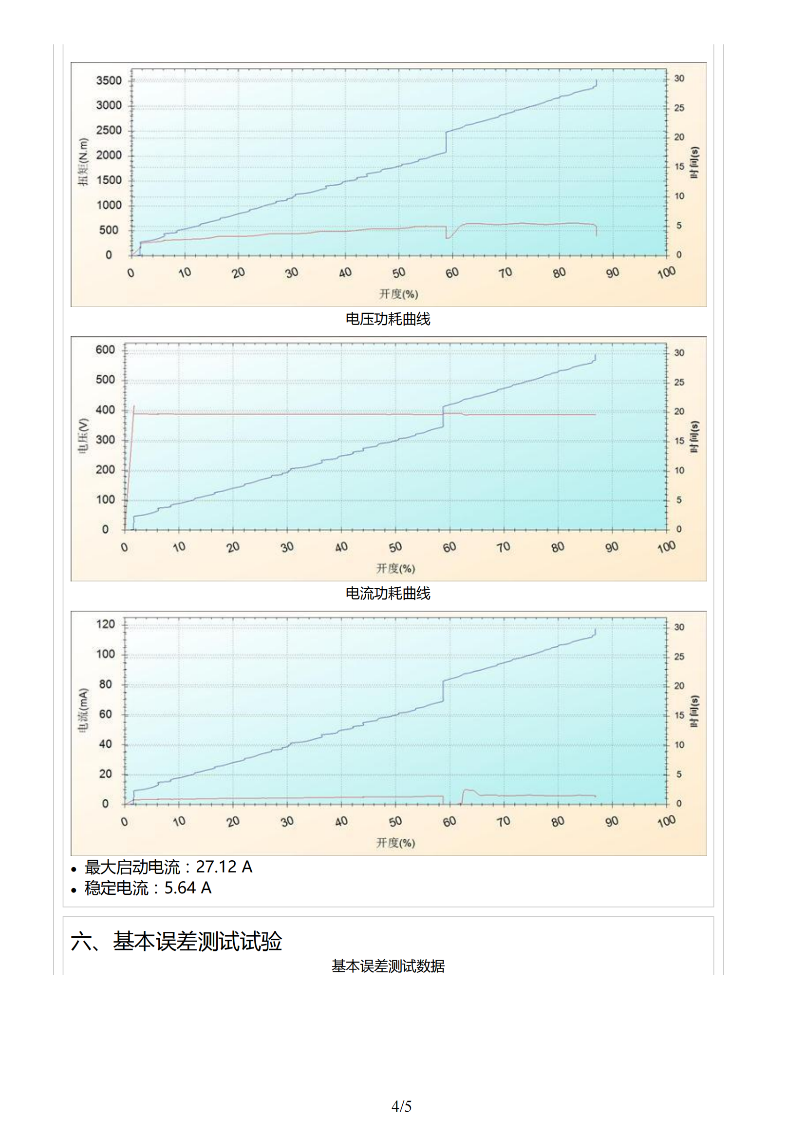
Used for type testing and factory inspection of electric devices. Testable items include: nominal torque test, locked-rotor torque test, maximum control torque test, minimum control torque test, starting torque test, torque repeatability deviation test, stroke repeatability deviation test, strength test, etc. At the same time, the three-phase voltage, current, and power factor of the motor are collected, and the active power, reactive power, and mechanical transmission efficiency are calculated;
Used for factory inspection of electric valves. Inspection items include: stroke detection, continuous testing items; torque and stroke curves are also drawn;
Used for factory inspection of pneumatic valves. Inspection items include: stroke detection, continuous testing items; torque, stroke, and pressure curves are also drawn;
Overview
The overall composition of this test device is shown in the figure below:
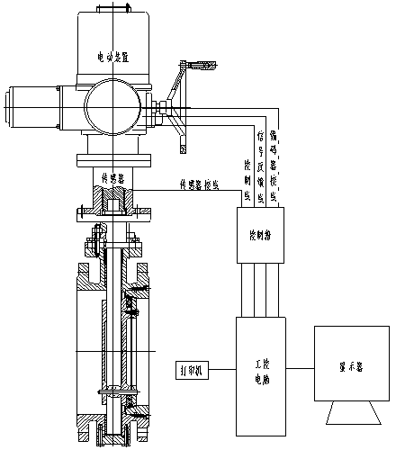
The valve is driven by a drive device (selected according to the test torque selected by the user). The drive device adopts an integral type. The operator can drive the valve using the button switch on the electric control box, or operate the drive device through computer software.
A torque sensor is connected between the drive device and the valve to measure the output torque of the drive device, that is, the rotation torque of the valve. The structure of the torque sensor adopts a non-contact slip ring type, so the accuracy is improved, and the service life is longer.
A pulse encoder is added and installed inside the drive device, which is directly connected to the output shaft. When the drive device is running, it can output two pulse signals with a phase angle difference of 90 degrees. The encoder outputs 1000 pulses per revolution per channel.
The wiring of the drive device, torque sensor, and pulse encoder are all summarized through an electric control box and then connected to an industrial control computer. In addition to the host computer, the computer system is also equipped with a 22-inch LCD monitor and a color inkjet printer.
Standard Configuration
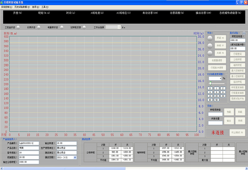
1. SM200 host computer control software
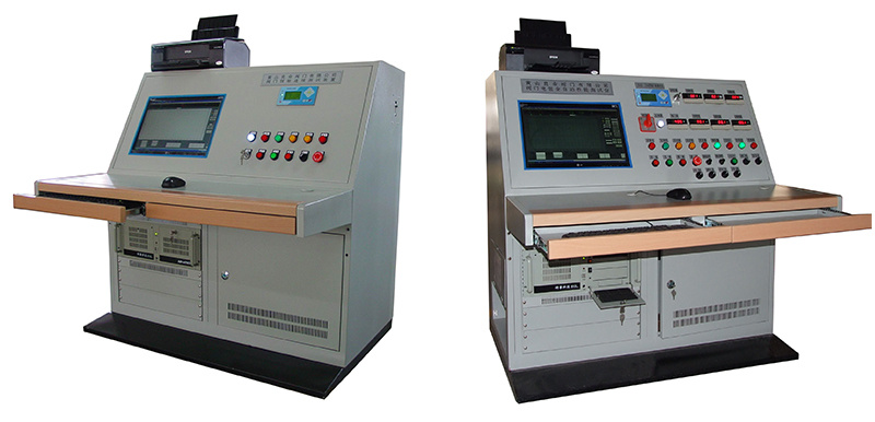
2. Control console: manual/automatic control unit, isolation transformer, contactor, intermediate relay, power filter
IPC610H industrial control computer, DELL E190S widescreen LCD monitor, Epson EPSON dot matrix printer
3. SM40-2100 bus controller
4. SM40-I/O-F industrial controller
5. SMTX-CE100 industrial Ethernet gateway
6. SM504 series dynamic torque sensors of various ranges
7. SM6000P-CAN-II intelligent power acquisition module
8. SMI precision current sensor (0~100A)
9. SM constant current power supply
Control Method
1. There are two control methods: manual control and computer control.
- The computer control system consists of a microcomputer and a programmable PLC controller, which is a two-level control system. The control principle is advanced, and an independent control unit is used, which truly realizes modular control.
The pressure can be accurately controlled, the pressure holding effect is good, and the pressure is automatically compensated in real time.
Test data and graphs are automatically recorded and saved in the computer.
- Manual control, PLC control, and computer control methods can be selected arbitrarily.
Test Items
1. Stroke setting test
2. Nominal torque test
3. Locked-rotor torque test
4. Maximum control torque test
5. Minimum control torque test
6. Starting torque test
7. Torque repeatability deviation test
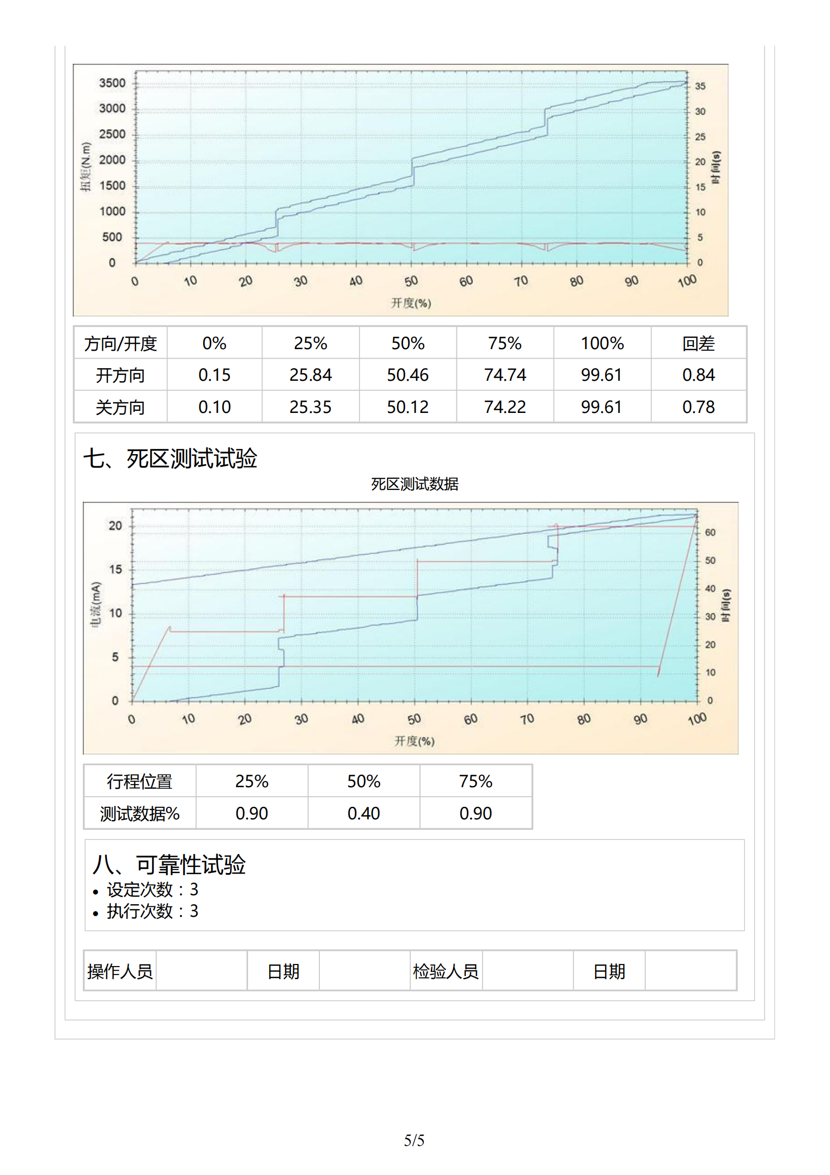
8. Stroke repeatability deviation test
9. Strength test
Features
1. Full quick-plug connector for easy testing
2. Real-time digital display of three-phase voltage and current
3. Online real-time monitoring of control current and feedback current
4. Internal and external power supply selection function
5. Switch quantity and analog quantity electrical equipment testing function
6. ESD testing function
7. The controller uses a full Chinese LCD display, which is simple and easy to learn
8. The controller has a PID adjustment function output, which can adjust the braking torque output of the magnetic powder brake in real time
9. Digital bus-type power acquisition (voltage, current)
10. CANBUS bus data link, ensuring data and system control real-time performance, communication rate up to 10M/s
11. Developed with VC++ advanced programming language, SQL SERVER real-time database
12. Rich human-computer interaction interface, simple and easy to understand operation
13. Users can define their own data report formats
Technical Indicators
1. Torque measurement range: 200~20000 Nm
2. System measurement accuracy: 1.0%
3. Stroke measurement accuracy: 1 degree
4. Power requirements: 220V±15% 50Hz 500W
5. Electrical component power supply: Determined by the user's electrical equipment
6. Ambient temperature: 0~60℃ Relative humidity: <90%RH (non-condensing)
7. Piano-style operating table: 1460*880*1350mm(W*D*H)
8. Voltage acquisition: 0~450VAC
9. Current acquisition: 0~100A
Keywords: Electric valve testing system, electric valve testing bench
Return

日月仪器
Contact Fax:0552-4070672
Company Website:www.sunmoon-china.com
Email:smsales@163.com
Address: No. 985, Xingzhong Road, High-tech Zone, Bengbu City, Anhui Province, China, Sun Moon Science and Technology Park
Made in China
