
 Language
Solutions
Application Solution
Automated Weighing and Packaging Solution for Grains and Feeds
Category:
Weighing solutions
Publish Time:
2020-07-09
Abstract
Automatic quantitative packaging scales are used in industrial and agricultural automated production for automatic quantitative packaging. The entire weighing process is controlled by a computer and is automatically completed. It features fast weighing speed, high weighing accuracy, labor saving, manpower saving, simple operation, and convenient maintenance. The new generation of packaging scale control system developed by Riyue Technology Development Group incorporates the advantages of related products at home and abroad, and adopts single-chip microcomputer technology and various anti-interference measures. It is mainly used for quantitative weighing of materials, quantitative packaging, and material flow control in the production process. It can adapt to various feeding methods such as spiral auger feeding, belt feeding, gate valve feeding, and vibrating feeder feeding, as well as packaging scales and quantitative scales with and without hoppers. It can achieve single feeding speed, double feeding speed, triple feeding speed, and continuously adjustable speed feeding control to meet the control needs of various packaging scales and quantitative scales.
Keywords: Automatic Packaging, Quantitative, Large and Small Feeding
1. System Composition
The quantitative packaging scale consists of a weighing unit, a trolley, a sewing and conveying device, a pneumatic system, a dust removal system, and a quantitative packaging control instrument. The key component affecting the packaging speed and accuracy is the weighing unit, which includes a hopper, a gate, a cut-off device, a weighing body, a bag clamping device, a bracket, and an electrical control device. The hopper is a buffer hopper, used for material storage and providing a nearly uniform material flow; the gate is located at the bottom of the hopper, used to block the material in the hopper when the equipment is under maintenance or malfunctions; the cut-off device consists of a cut-off hopper, a cut-off gate, pneumatic components, and an air replenishment valve, providing large, medium, and small three-level feeding during the weighing process. The material flow of large, medium, and small feeding can be adjusted separately to ensure that the quantitative packaging scale meets the accuracy and speed requirements of measurement; the function of the air replenishment valve is to balance the air pressure difference in the system during weighing; the weighing body mainly consists of a weighing hopper, a load-bearing bracket, and a weighing sensor, completing the conversion of weight to electrical signals and transmitting them to the control unit; the bag clamping device mainly consists of a bag clamping mechanism and pneumatic components, used to clamp the packaging bag so that the weighed material completely falls into the packaging bag; the electrical control device consists of a weighing display controller, electrical components, and a control cabinet, used to control the system operation, making the entire system work in an orderly manner according to the preset program.
2. Working Principle
2.1 Hopper Feeding Method 1
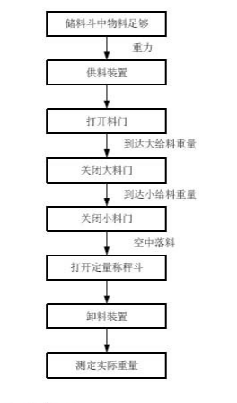
When the discharge gate is in place and the input signal is valid, feeding can begin, with large, medium, and small feeding simultaneously. The feeding amount is detected. When it is greater than or equal to the large feeding threshold, large feeding stops. After a large feeding delay, medium feeding is detected. When it is greater than or equal to the medium feeding threshold, medium feeding stops. After a medium feeding delay, small feeding is detected. When it is greater than or equal to the small feeding threshold, small feeding stops. After a small feeding delay, it is determined whether the system is stable. If the system is not stable within the stable judgment time, it indicates that the system disturbance is too large. If it is stable, weighing begins directly, and it is determined whether the feeding is excessive or insufficient. After weighing is completed, if there is a discharge permission signal input, the door opens for discharge. After the discharge delay time, the door closes. After closing, the zero point weighing delay is measured to the zero point, and then the next work cycle begins. After closing, the bag placement delay begins, and the bag is placed when the time is up.
2.2 Non-Hopper Feeding Method 2
The bag placement signal output is invalid (also bag clamping), the discharge permission signal input is valid, and the zero point weighing delay is measured to the zero point. If the system is unstable, the zero point is not saved this time, and the last zero point is still used for weighing. If it exceeds the zero point error range, an alarm will stop the machine. If the zero point is normal, feeding begins, with large, medium, and small feeding simultaneously. The feeding amount is detected. When it is greater than or equal to the large feeding threshold, large feeding stops. After a large feeding delay, medium feeding is detected. When it is greater than or equal to the medium feeding threshold, medium feeding stops. After a medium feeding delay, small feeding is detected. When it is greater than or equal to the small feeding threshold, small feeding stops. After a small feeding delay, it is determined whether the system is stable. If the system is not stable within the stable judgment time, it indicates that the system disturbance is too large. If it is stable, weighing begins directly, and it is determined whether the feeding is excessive or insufficient. If it is not excessive or insufficient, the bag placement delay begins, and the bag is placed when the time is up. A new work cycle begins.
2.3 Belt Feeding Method 3
The bag placement signal output is invalid (also bag clamping), the discharge permission signal input is valid, and the zero point weighing delay is measured to the zero point. If the system is unstable, the zero point is not saved this time, and the last zero point is still used for weighing. If it exceeds the zero point error range, an alarm will stop the machine. If the zero point is normal, feeding begins, with large, medium, and small feeding simultaneously, and the belt feeding starts. The feeding amount is detected. When it is greater than or equal to the large feeding threshold, large feeding stops. After a large feeding delay, medium feeding is detected. When it is greater than or equal to the medium feeding threshold, medium feeding stops. After a medium feeding delay, small feeding is detected. When it is greater than or equal to the small feeding threshold, small feeding stops, and the pre-feeding delay starts. When the time is up, the belt feeding is closed. After a small feeding delay, it is determined whether the system is stable. If the system is not stable within the stable judgment time, it indicates that the system disturbance is too large. If it is stable, weighing begins directly, and it is determined whether the feeding is excessive or insufficient. If it is not excessive or insufficient, the bag placement delay begins, and the bag is placed when the time is up. A new work cycle begins.
2.4 Cement Packaging Method 4
The bag placement signal output is invalid (also bag clamping), the discharge permission signal input is valid, feeding begins, with large, medium, and small feeding simultaneously. When the feeding limit is reached, the bag placement delay begins, and the bag is placed when the time is up.
3. Functional Characteristics
(1) High-precision Σ-△ A/D conversion, 1,000,000 codes, high-speed sampling 200 times/second.
(2) The instrument has functions such as [System Settings], [Parameter Settings], [Calibration Function], [Interface Test], and [Manual/Automatic Switching].
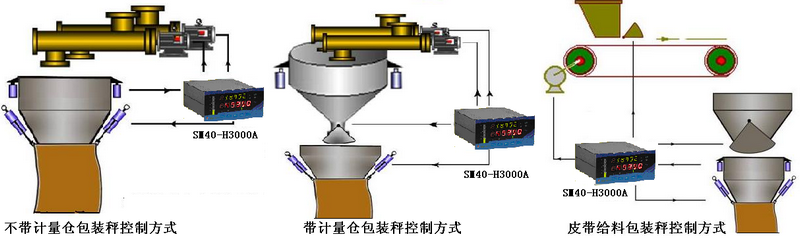
(3) It can adapt to various feeding methods such as spiral auger feeding, belt feeding, gate valve feeding, and vibrating feeder feeding. The feeding speed can be selected as single feeding speed, double feeding speed (large and small feeding), and triple feeding speed (large, medium, and small feeding), or a speed-type feeder can be selected, with continuously adjustable feeding speed.
(4) Weighing methods with or without hoppers can be selected.
(5) All intelligent control algorithms are used to effectively reduce the interference of various random errors and eliminate the influence of various abnormal situations.
(6) It has weight calibration and dynamic physical verification functions. Manual or automatic zero point measurement functions can be selected. For cement packaging machines, the instrument also has an intelligent zero point measurement function.
(7)It can complete the entire batching process, including tare weight measurement, coarse feeding, fine feeding, static weighing, error calculation, alarm processing, unloading, compensation calculation, and cumulative processing. The running program can be started or stopped via keyboard and external signals, and materials can be manually added or unloaded via the manual/automatic key.
(8)Batch control: Performs cumulative counting control and automatically stops working after reaching the preset value.
(9)Large cycle control: Records the actual error value each time and accumulates it, adjusting the actual feeding amount for the next time to minimize the overall cycle and error value.
(10)Interface testing function: Allows manual testing of the instrument's own interface or remote interface.
(11)Settings allow for clearing the total weight accumulation, non-clearable total weight accumulation, and clearable bag count accumulation.
(12)Timed unloading function: Sets the unloading time for quantitative bag unloading.
(13)Standard RS-485 communication interface; optional support for multiple communication protocols such as DEVICENET, MODBUS, and PROFIBUS.
(14)Multiple operation methods are available, including instrument keyboard, external signals (ports), and host computer communication.
4. Technical Indicators
(1)Linear error: <0.01%F·S
(2)System accuracy: <0.05%
(3)Applicable load cell types: All general-purpose load cells (All products are factory-calibrated with precise digital calibration of the sensor sampling channels for power supply, amplification, and acquisition, ensuring good interchangeability between instruments).
(4)Load cell power supply: 10VDC, can connect 8 350Ω sensors in parallel.
(5)OC gate output: Pull-up effective. Allowable current 500mA, cutoff voltage 55VDC, allowable power consumption: 625mW at 25℃, decreasing by 5mW/℃ above 25℃.
5. Process Flow Diagram
6. Application Topology Diagram
7. Timing Diagram
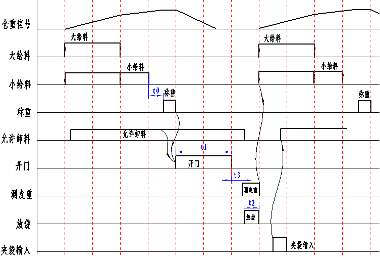
Timing Diagram with Hopper Control
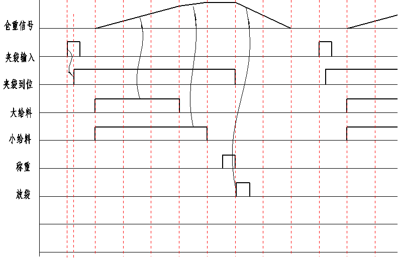
Timing Diagram without Hopper Control
Keywords: Automatic packaging, quantitative, and sized feeding
Previous:

日月仪器
Contact Fax:0552-4070672
Company Website:www.sunmoon-china.com
Email:smsales@163.com
Address: No. 985, Xingzhong Road, High-tech Zone, Bengbu City, Anhui Province, China, Sun Moon Science and Technology Park
Made in China
