
 Language
Solutions
Application Solution
Highway Weigh-in-Motion (WIM) System Solution
Category:
Weighing solutions
Publish Time:
2020-07-09
Abstract
With the continuous deepening of highway weigh-in-motion charging and overload control work, weigh-in-motion systems have been increasingly widely used in highway weigh-in-motion charging. Currently, in the research and development of weigh-in-motion systems in China, due to the lack of experience in systematically analyzing various factors affecting weigh-in-motion systems, the accuracy of weigh-in-motion systems is relatively low in practical applications, especially when the vehicle speed is high, the weigh-in-motion error is even greater, and the measurement accuracy does not meet the requirements. Therefore, the measurement accuracy of the weigh-in-motion system is the main problem in the application of highway weigh-in-motion charging and overload control. Ruyue Science and Technology Development Group is a high-tech enterprise in China engaged in the research and development and production of weighing instruments. After years of practice, we can provide you with a complete set of solutions for vehicle scales and their peripheral control systems.
Keywords: Highway, Weigh-in-Motion, Weighbridge, Axle Detector, Vehicle Separator, Detection Coil
1. System Classification
Weigh-in-motion systems can be classified according to the type of sensor used: bending plate weigh-in-motion system and piezoelectric sensor weigh-in-motion system.
(1) The bending plate weigh-in-motion system uses a metal plate with strain gauges attached to the bottom for weighing. When a vehicle passes over the bending plate, the system measures the strain generated by the strain sensor, and uses this to calculate the dynamic weight value, and then predicts the vehicle's true axle weight. Using the bending plate for measurement, the static weight is obtained by estimating the dynamic load and calibration parameters. The calibration parameters are determined by several influencing factors, such as vehicle speed and road surface, which are used in estimating the static load.
(2) The piezoelectric weigh-in-motion system uses pressure sensors to detect voltage changes caused by the pressure on the sensor from the axle weight to measure the axle weight. When a vehicle passes over the pressure sensor, the system records the voltage change of the sensor and calculates the dynamic load. The static load is obtained by estimating the dynamic load and calibration parameters. When measuring the axle weight of a vehicle traveling at high speed, because the width of the sensor is very small, when the wheel passes over the strip sensor, regardless of the vehicle speed, although the acquisition time is different, the information on the tire contact length is collected for all vehicles, and the complete signal output from the sensor constitutes the estimated value of the axle weight.
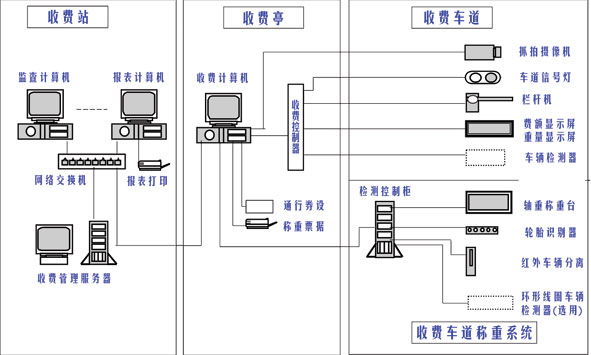
2. System Composition
The weigh-in-motion system currently used on toll lanes usually consists of five parts: a weigh-in-motion weighbridge, an axle detector, a vehicle separator, a detection coil (optional), and a data control cabinet. It is used to detect and measure freight vehicles, and can accurately measure information such as axle weight, number of axles, total vehicle weight, vehicle speed, and passage time.
(1) Weigh-in-motion platform: This is the key system of the weigh-in-motion charging system, used to measure the axle weight of each axle and the total weight of the vehicle and cargo while the vehicle is in motion.
(2) Vehicle separator: Used to distinguish between adjacent vehicles, providing the start and end signals for a complete transaction.
(3) Axle identifier consists of sensors arranged at regular intervals and a data collector. It is arranged in a linear array on one side in front of the weighbridge to detect the tire width of each axle of the vehicle passing through the weighing detection area, and cooperates with the weighing detection weighbridge to complete the identification of the coupled axle type. (4) The data control cabinet is used to receive and process signals and data from various detection systems, and uploads the processed results such as vehicle weight and vehicle type to the toll system computer.
(5) Ring coil: The ring coil detector consists of three parts: a ring coil sensor embedded in the road surface, a signal detection and processing unit (including a signal amplification unit, a data processing unit, and a communication interface), and a feeder. It is mainly used to prevent pedestrians from blocking the grating and triggering the system to work, detect vehicle reversing, and replace the grating for vehicle separation in extremely bad weather such as heavy fog;
3. System Working Principle
After the vehicle enters the toll lane, its axles pass through the ring coil, axle identifier, weighing platform, and infrared vehicle separator laid in the road surface in sequence at low speed. The axle identifier detects the tire width of each axle of the vehicle passing through the weighing detection area, judges the single or double tire information, the sensors under the weighing weighbridge will detect the axle weight information and other weighing signals, and the vehicle separator can accurately determine whether the vehicle has completely passed. When the vehicle completely leaves, the control cabinet processes the vehicle weighing signals from the weighing system to form a complete vehicle weighing information, which includes the vehicle's axle type, axle weight, coupled axle information, number of tires per axle, coupled axle weight, wheelbase, speed, and total weight. Then, it transmits the vehicle's weighing information to the toll lane computer through the data interface, and the toll lane computer calculates the vehicle's toll based on the obtained information data.
From the entire working principle above, it can be seen that in the case of networked toll collection, the weighing accuracy and whether the vehicle type judgment of the weighing system is correct will directly affect the toll collection. The accuracy of its dynamic weighing is not only related to the various components of the equipment itself, including the accuracy of the hardware and software design, but also related to the installation and debugging of the dynamic weighing system and the driving status of the measured vehicles on the lane.
4. Functional Characteristics
(1) The weighbridge adopts unique anti-impact and logic identification technology, which can effectively resist frequent impacts to ensure the accuracy and service life of dynamic weighing, and can correctly handle complex driving states such as starting, braking, and reversing during weighing to deal with malicious cheating behavior of vehicles.
(2) The box girder weighbridge adopts four 20t load cells, with a load capacity of 80t. Combined with the box girder structure of the weighbridge, it can resist the long-term and frequent rolling of heavy vehicles. It adopts shallow pit installation and has dust-proof function, small maintenance amount, and simple and easy maintenance work.
(3) The bending plate weighbridge adopts alloy steel elastomer, which is impact-resistant and has a long service life. Special sealing prevents erosion from accumulated water; easy installation and minimal damage to the road surface.
(4) The infrared light curtain adopts products from internationally renowned manufacturers, with automatic heating of the window glass, automatic temperature and humidity control, and anti-condensation and anti-frosting.
5. Technical Indicators
(1) The dynamic and static weighing system has static and dynamic weighing functions: static weighing is manual, and dynamic weighing is automatic. Dynamic mode can also be used for static weighing.
(2) Single-axle weighing range: 2000~30000㎏
(3) Resolution: 10㎏
(4) Overload capacity: 150%
(5) Static weighing accuracy: Class Ⅲ
(6) Dynamic weighing accuracy: For total vehicle and cargo weight of 4t~80t, vehicle speed ≤5km/h at a constant speed, the dynamic weighing accuracy is Class 2 according to international standards.
6. System Application Diagram
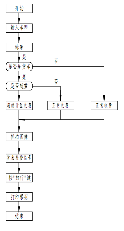
7. System Workflow Diagram
8. Software Function Introduction
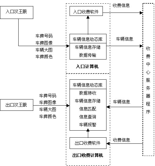
The system is based on network data transmission. The entrance, exit, and information center transmit information via the network, and data is exchanged between the charging software and the dynamic library.

Software Interface
Keywords: Highway, dynamic weighing, weighbridge, axle detector, vehicle separator, detection coil
Return

日月仪器
Contact Fax:0552-4070672
Company Website:www.sunmoon-china.com
Email:smsales@163.com
Address: No. 985, Xingzhong Road, High-tech Zone, Bengbu City, Anhui Province, China, Sun Moon Science and Technology Park
Made in China
