
 Language
Products
PRODUCT CENTER

Load sensor SMA35GDDC-B
The load sensor is specifically designed for load testing at the suspension point of oilfield pumping units. It has been continuously improved through use. Its U-shaped, direct-insertion structure with anti-脱落 (translation not possible) bolts ensures convenient and quick installation and removal. Standard signal output ensures good interchangeability. The two-wire 4~20mA system transmits power and signals simultaneously, with self-adaptive polarity. Quick-connect terminals facilitate convenient on-site wiring and high cable reuse. The fully sealed, waterproof design allows for all-weather use. Accompanying engineering installation accessories such as handles and cable rings protect the cables and terminals, ensuring the quality of cable installation and wiring during the long-term operation of the pumping unit.
Category:
Description Overview
SMA35GDDC-B Type Load Sensor Specifically designed for load testing at the suspension point of oilfield pumping units, constantly improved through use; U Type plug-in structure, anti-脱螺栓 lock, convenient and quick installation and disassembly. Standard signal output, good interchangeability. Two-wire 4~20mA, power supply and signal transmission at the same time, polarity adaptive; Quick wiring terminal, convenient and quick on-site wiring, high cable reuse rate; Fully sealed waterproof design, suitable for all-weather use; Matching engineering installation accessories such as handle hooks and winding rings protect the cables and terminals, ensuring the construction quality of cable installation and wiring during the long-term operation of the pumping unit.
Main Technical Indicators
Table 1. Main Technical Indicators of SMA35GDDC-B Type Load Sensor
|
Item Item |
Technical Parameters Parameters Parameters |
Unit Unit |
|
Output |
4 ~ 20 |
mA |
|
Power Supply |
15 ~ 30 (Recommended 24 ) |
VDC |
|
Range |
0~150 |
kN |
|
Insulation Resistance |
≥ 5000 |
M Ω |
|
Operating Temperature |
- 40 ~+ 85 |
℃ |
|
Accuracy |
0.5 |
%F · S |
|
Allowable Overload |
150 |
%F · S |
|
Protection Level |
IP67 |
|
External Structure
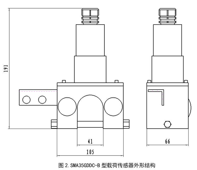
Instructions for Use
1. When determining the sensor specifications, it is recommended to select according to the rated load of 80% Select.
2. When designing the loading device, ensure that the line of action of the loading force coincides with the force axis of the sensor to avoid measurement errors caused by lateral forces.
3. Two-wire output, no positive and negative polarity wiring. After the sensor is connected to the power supply, it must be preheated, and after the instrument stabilizes, start working.
4. The sensor housing, protective cover, and lead connector are all sealed. Please do not open them arbitrarily.
5. The sensor storage environment should be dry and free of corrosion. Avoid using the sensor near high non-working heat sources.
Installation
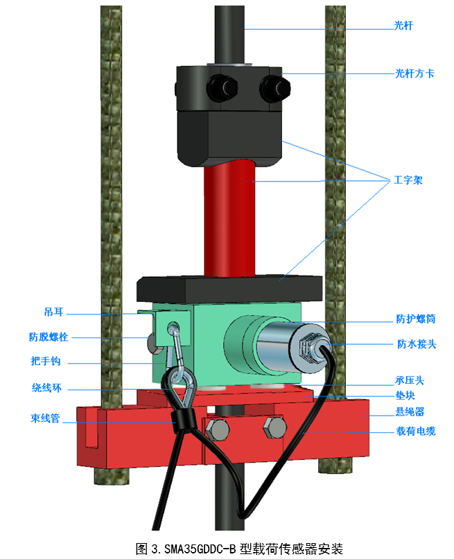
SMA35GDDC-B Type load sensor is installed between the suspension device and the square card on the polished rod, locked by anti-脱螺栓. As shown in Figure 3 The installation steps are as follows:
1. Stop the pumping unit about 30cm from the bottom dead center (wellhead) and engage the brake.
2. Fix the square card at the wellhead to secure the polished rod, release the brake, start the pumping unit until the suspension device is unloaded (i.e., the polished rod square card is separated from the I-beam), then immediately stop the machine and engage the brake again.
3. Sensor pressure head ( 2 a protruding cylinder) downwards, U insert into the space between the lower plate of the I-beam and the suspension device.
4. Hold the sensor, suspension device, and I-beam upright, with the upper and lower plates of the I-beam parallel and correctly installed on the suspension device. Note: If the upper surface of the suspension device is not flat, shims can be added to ensure that the center line of the sensor pressure head is perpendicular to the polished rod.
a. Ensure that the sensor installation does not change the test structure of the I-beam (the test worker inserts the hydraulic sensor here, and the accompanying portable instrument is used for power measurement). b. Release the brake
5. Release and engage the brake repeatedly, controlling the slow upward movement and stable loading of the suspension device. , Remove the fixed square card and smooth the scratches on the polished rod.
6. Installation of the load cable: Select high-heat-resistant, high-cold-resistant, and bend-resistant materials, outer diameter. The cable clamp is wound around the winding ring, and the cable is bundled tightly with a cable tie.
7. Lead-out:
The cable is led out about
- long near the sensor end, inserted into the waterproof connector, and into the protective sleeve (unscrewed beforehand). Connect the wire ends to the terminals of the sensor; 40cm Tighten the protective sleeve onto the sensor, and tighten the waterproof connector;
- Use the handle hook to pass through the winding ring and hang it on the lug;
- 以把手钩穿过绕线环,挂在吊耳上;
- The other end of the load cable is generally fastened to the operating platform at the top of the pumping unit support. The length of the cable from the sensor to the operating platform should be appropriate; generally, when the oil well is at its lower dead center, the lowest point of the suspended cable should be slightly below the sensor. It should not be too loose or too tight.
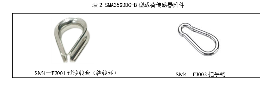
Sensor Accessories
Keywords:
Related Applications

undefined

日月仪器
Contact Fax:0552-4070672
Company Website:www.sunmoon-china.com
Email:smsales@163.com
Address: No. 985, Xingzhong Road, High-tech Zone, Bengbu City, Anhui Province, China, Sun Moon Science and Technology Park
Made in China
