
 Language
Products
PRODUCT CENTER

Telemetry indicator SM35AWS-FL
The SM35AWS-FL telemetry indicator is designed for pump jack well indicator diagram testing. It integrates load and acceleration displacement measurement, low-power embedded microcontroller, and low-power long-distance wireless digital communication technology into a high-performance wireless sensor product. It is one of the important front-end acquisition devices in the construction of digital oilfield oil and gas production Internet of Things, developed with the advancement of the low-power wireless communication network technology LoRaWAN. It uses its own load sensor and acceleration sensor to periodically and synchronously measure the load of the pump jack suspension point and the displacement of the polished rod, accesses the LoRaWAN communication network, and realizes the direct remote transmission of the work diagram data characterizing the working condition of the pump jack well.
1. Overview
The SM35AWS-FL telemetry indicator is designed for pump jack well indicator diagram testing. It integrates load and acceleration displacement measurement, low-power embedded microcontroller, and low-power long-distance wireless digital communication technology into one high-performance wireless sensor product. With the advancement of low-power wireless communication network technology LoRaWAN, it is one of the important front-end acquisition devices in the construction of digital oilfield oil and gas production Internet of Things. It uses its own load sensor and acceleration sensor to perform periodic online synchronous measurement of the pump jack suspension point load and sucker rod displacement, accesses the LoRaWAN communication network, and realizes the direct remote transmission of indicator diagram data characterizing the pump jack well operating conditions.
Its high-reliability design suitable for industrial environments, as well as its high precision, simple installation, easy maintenance, environmental protection, and durability, have won user recognition. It has been widely promoted and applied in major oilfields in China, including Shengli, Daqing, Huabei, Changqing, Xinjiang, and Qinghai, and has also been partially applied in overseas oil companies. This product has obtained multiple patents and has independent intellectual property rights. Counterfeiting will be investigated.
2. Technical Indicators
2.1. Operating Environment:
Ø Temperature, -40~70℃; Relative humidity, 0~100%RH; Atmospheric pressure, 86~106 kPa;
Ø Vibration, 10~500Hz, peak acceleration <19.6m/s2;
Ø AC external magnetic field ≤400A/m.
2.2. Power Supply:
Ø HYLB-1555 lithium battery pack, maximum open-circuit voltage, 3.6V; maximum short-circuit current, 100mA;
Ø Polycrystalline silicon solar panel, 173 mm×135 mm ×5mm; maximum open-circuit voltage 4.2V; maximum short-circuit current 100mA.
2.3. Measurement Performance:
Ø Load, range: 0~150kN, accuracy: 0.5%F.S, overload capacity: ≥1.5F.S; stability: ±0.1%FS/year;
Ø Acceleration displacement, range: 1~12m, accuracy: 2.0% F.S; strokes: minimum 1 stroke/minute, accuracy: 1%;
Ø Maximum indicator diagram sampling points 255, sampling cycle ≥10 minutes, configurable; well start/stop alarm.
2.4. Two Wireless Communication Methods:
Ø ZigBee or SMSF (local communication): Transmission distance (open space line of sight) ≥300m; RF transmission power ≤10mW(+10dBm); Receiving sensitivity: -103dBm; Operating frequency ISM2.4~2.5GHz communication protocol, ZigBee PRO 2007 or SMSF; Customizable according to needs.
Ø LoRaWAN (long-distance communication): Transmission distance (open space line of sight): 3500m; RF transmission power: ≤100mW(+20dBm); Receiving sensitivity: -140dBm; Operating frequency 470~510MHz.
2.5. Explosion-proof Mark: Ex ib II C T4 Gb,Explosion-proof certificate number: CE18.2244X; Protection level: IP68 (water depth 1m, duration 1h).
2.6. Dimensions: Length × Width × Height = 210 mm × 105 mm × 75mm; U-shaped opening size: Standard 40mm, customizable.
2.7. Weight: 4.6kg.
3. External Structure
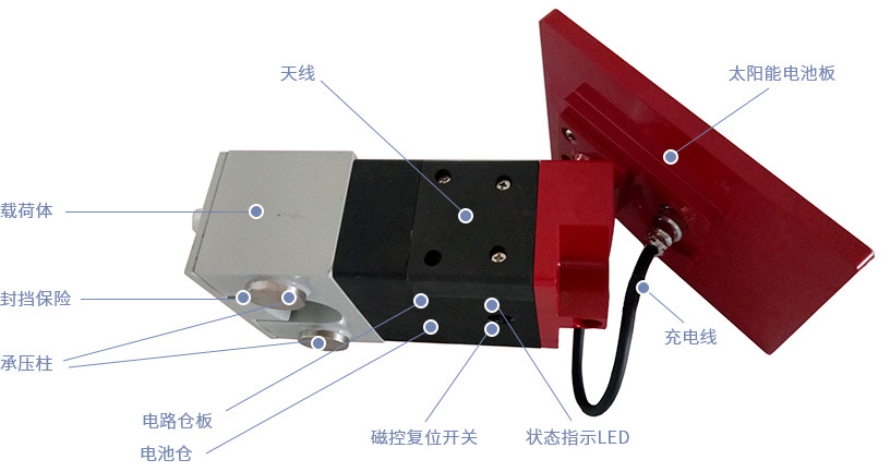
Figure 2. Functional Component Indication Diagram of SM35AWS-FL Telemetry Indicator
4. Quick Start Guide
4.1 LED Status Indication
|
Status LED |
Status Description |
Sensor Status |
Remarks |
|
Red |
Flashes 3 times at 0.4s intervals |
Reset |
Indication after power-on or successful reset via magnetic control reset switch (magnet close to "reset" indicator position for 3s). |
|
Steady on for 2~20s |
Joining ZigBee network network |
Indicator for joining the ZigBee network after the sensor is powered on or reset for the first time. |
|
|
Steady on for more than 20s until exit |
Successfully entered configuration mode |
Configure common parameters, instrument calibration, indicator diagram control parameters, and sampling cycle. |
|
|
Flashes at 1s intervals |
Active Status |
|
|
|
Flashes 3 times at 0.4s intervals, repeating at 1s intervals |
Low Battery |
Low battery alarm. |
|
|
Green |
Steady on |
Indicator diagram measurement in progress |
Continuous process for at least one stroke cycle or more |
|
Flashes at 1s intervals |
Sending regular sequences |
After successfully joining the LoRa (memory) network, send the regular sequence. After each transmission, wait for the base station to respond. If there is no response after a 30-second timeout, resend. Maximum 3 attempts. |
|
|
Send power curve data packet |
After the power curve measurement is complete, and with the LoRa (memory) network successfully joined, transmit the power curve data packet in multiple packets. Each data packet transmission requires base station confirmation; otherwise, resend. The entire process, depending on network communication conditions, may last up to 30 minutes. |
4.2 Installation
1) Configure well name and well site configuration (establish a local wireless data communication network with the RTU); Note: Only for ZigBee wireless communication mode.
2) To ensure power curve transmission efficiency and reduce sensor battery power consumption, please reasonably arrange the base station distance to ensure that the signal strength RSSI ≥ -110dBm when the terminal sensor is working normally.
3) Have a professional place the sensor horizontally between the suspension device pressure blocks according to the direction indicated by the "installation direction marking", ensuring that the "pressure column" is evenly loaded; after installation, be sure to reliably fasten the "blocking insurance" with the matching screws.
4) Use our company's matching test software to immediately conduct a power curve test at the well site. See the "SM Series Digital Wireless Sensor Operation Manual" for details.
5.3 Precautions
1) If the load sensor is not used for a long time, please disconnect the battery or set the measurement type to deep sleep mode and restore it when using it.
2) If problems occur during the use of the product, please contact our company's technical service personnel in time; do not disassemble the sensor yourself, otherwise, the warranty will be void!
3) The battery pack used in this sensor is a product provided by our company that has passed explosion-proof certification. If you replace it with other battery packs not provided by our company, our company cannot continue to guarantee the explosion-proof performance of this product, and we will no longer be responsible for any risks and consequences!
4) Please familiarize yourself with the "SM Series Digital Wireless Sensor Operation Manual" before performing on-site debugging operations.
Keywords:
Load sensor
sensor
Related Applications

undefined

日月仪器
Contact Fax:0552-4070672
Company Website:www.sunmoon-china.com
Email:smsales@163.com
Address: No. 985, Xingzhong Road, High-tech Zone, Bengbu City, Anhui Province, China, Sun Moon Science and Technology Park
Made in China
